


ELECTRICAL
10.20
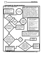
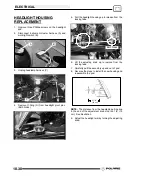
TEST 3: Measure AC Voltage Output of Each
Stator Leg at Charging RPM
1. Set the selector dial to measure AC Voltage.
2. Start the engine and let it idle.
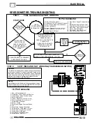
3. While holding the ATV at a specified RPM,
separately measure the voltage across each ’leg’
of the stator by connecting the meter leads to the
wires leading from the alternator (Y1 to Y2, Y1 to
Y3, Y2 to Y3).
4. Refer to the table below for approximate Voltage
AC readings according to RPM. Test each leg at
the specified RPM in the table.
Example
: The
alternator current output reading should be
approximately
18 Vac at 1300 RPM between
each ’leg’
.
NOTE:
If one or more of the stator leg output AC
voltage varies significantly from the specified value,
the stator may need to be replaced.
ATV RPM
Reading
AC Voltage (Vac)
Reading
1300
18 Vac
±
25 %
3000
42 Vac
±
25 %
5000
64 Vac
±
25 %
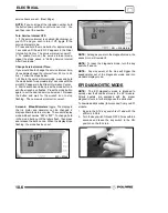
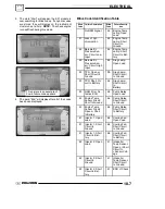
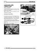
RELAYS
These relays, located next to the ECU, assist with
component operation such as the fan, fuel pump, etc.
The fan relay, controlled by the ECU, operates the fan.
The power relay, controlled by the ECU, turns on
power for components such as the fuel pump,
injectors, etc.
Fused 20--amp, unswitched FAN power supply.
Fan ’ON’ Command. Ground is supplied by the ECU,
closing the relay to turn on the fan.
KEY--ON Battery power supply, switched on by the key
and LH control switches, enables power to relay.
Relay ’ON’ command. The ECU supplies a ground
which closes the relay, supplying power to run the fuel
pump, injectors, etc.
EFI power output. ’ON’ when ECU sends a signal on the
GRY/W wire, closing the relay. Supplies 15--amp power
for ECU--controlled operation of EFI components.
Fused 15--amp, unswitched battery power IN supply for
EFI component operation.
Fan power output. ’ON’ when the ECU sends a signal
on the Y/BLK wire, closing the relay. Supplies 20--amp
power for fan operation.
RED
YELLOW / BLK
RED / WHITE
FAN RELAY
POWER RELAY
ORANGE/BLK
RED / WHITE
KEY--ON Battery power supply, switched on by the
key and LH control switches, enables power to relay.
Tied to Fan Relay terminal.
GRAY/WHITE
ORANGE
RED/BLK
Summary of Contents for Sportsman 800 Efi 2005
Page 116: ...ENGINE 3 62 NOTES ...
Page 136: ...FUEL SYSTEM FUEL INJECTION 4 20 NOTES ...
Page 186: ...CLUTCH 6 30 NOTES ...
Page 256: ...BRAKES 9 24 NOTES ...
Page 292: ...ELECTRICAL 10 36 BASIC WINCH WIRING 2005 ATV MODELS 2005 ATV WINCH WIRING DIAGRAM ...
Page 300: ...ELECTRICAL 10 44 NOTES ...
Page 301: ...ELECTRICAL 10 39 WIRING DIAGRAM 2005 SPORTSMAN 700 800 EFI Stator ...
Page 302: ...ELECTRICAL 10 40 WIRING DIAGRAM 2005 SPORTSMAN 700 800 EFI ...