


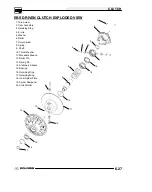


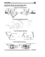


FINAL DRIVE
7.2
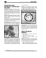
WHEEL AND HUB TORQUE
TABLE
COMPONENT
FT. LBS.
(IN.LBS.)
NM
F/R
Steel
Wheel Nuts
30
41
F/R
Aluminum
Wheel Nuts
90
122
Front Hub Nut
70
95
Rear Hub Nut
80
109
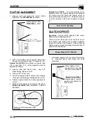
CAUTION:
Locking nuts, and bolts with preapplied
locking agent should be replaced if removed. The
self-locking properties of the nut or bolt are reduced
or destroyed during removal.
SPECIAL TOOLS
PART NUMBER
TOOL
DESCRIPTION
2872608
Roller Pin
Removal Tool
8700226
CV Boot Clamp
Pliers
2870772
1 3/4” Straight
Wrench
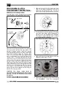
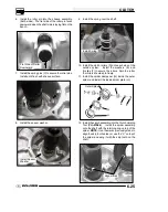
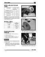
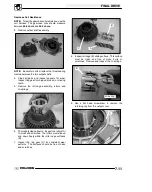
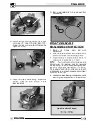
FRONT DRIVE AXLE
REMOVAL
1. Set the ATV in park. Remove hub dust cap.
2. Remove cotter pin.
3. Loosen the hub retaining nut.
4. Loosen - but do not remove - the wheel nuts.
5. Safely lift and support the front of the ATV.
CAUTION:
Serious injury could occur if machine tips or falls.
6. Remove wheel.
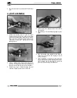
7. Remove the two brake caliper attaching bolts.
CAUTION:
Do not hang the caliper by the brake
line. Use wire to hang the caliper to prevent
possible damage to the brake line.
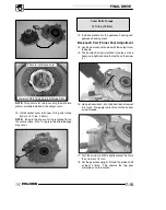
8. Remove hub.
9. Remove cotter pin and nut from lower A-arm ball
joint. Remove lower A-arm from ball joint.
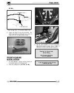
10. Pull strut assembly out while pivoting front drive
shaft downward until it clears strut assembly.
Summary of Contents for Sportsman 800 Efi 2005
Page 116: ...ENGINE 3 62 NOTES ...
Page 136: ...FUEL SYSTEM FUEL INJECTION 4 20 NOTES ...
Page 186: ...CLUTCH 6 30 NOTES ...
Page 256: ...BRAKES 9 24 NOTES ...
Page 292: ...ELECTRICAL 10 36 BASIC WINCH WIRING 2005 ATV MODELS 2005 ATV WINCH WIRING DIAGRAM ...
Page 300: ...ELECTRICAL 10 44 NOTES ...
Page 301: ...ELECTRICAL 10 39 WIRING DIAGRAM 2005 SPORTSMAN 700 800 EFI Stator ...
Page 302: ...ELECTRICAL 10 40 WIRING DIAGRAM 2005 SPORTSMAN 700 800 EFI ...