Polaris RANGER EV 2015 Service Manual Download Page 27

9926595 R01 - 2015-2016

RANGER

EV Service Manual

© Copyright Polaris Industries Inc.

1.21

terminal. Permanent battery damage can result from lack
of terminal maintenance.

Over-tightening

of

terminal

fasteners

can

cause

permanent damage to the battery.
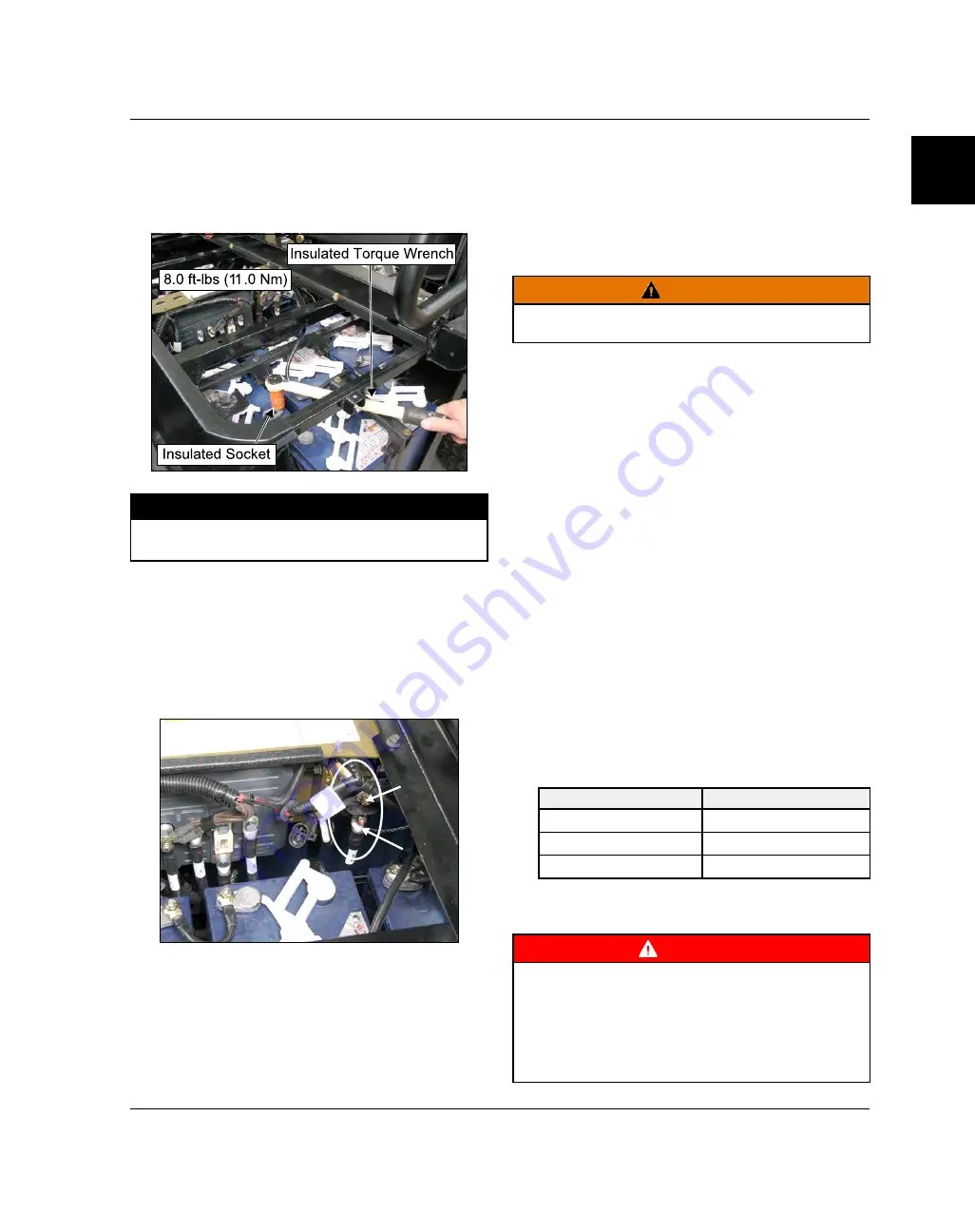
TORQUE

Battery Cable Terminals:

8.0 ft-lbs (11.0 Nm)

Battery

Contactor Terminals:

8.0 ft-lbs (11.0 Nm)

BATTERY CONTACTOR FASTENER
TORQUE

Torque contactor fasteners using insulated tools as
described for the battery terminals above.

Loose

or

over-tightened

contactor

terminals

can

permanently damage the contactor.

BATTERY CLEANING (EXTERNAL
SURFACES)

1.

Turn key OFF.

2.

Remove seat and storage trays.

3.

Disconnect the main electrical connector.

4.

Check to be sure battery caps are in place and
securely latched in the closed position. SeeBattery
Water Level, page 1.22 
for vent cap operation.

5.

Mix a solution of one tablespoon baking soda per
one cup of clean water. Wash battery case with
solution to remove acid residue, dirt, and debris.

CAUTION

Do not allow cleaning solution or tap water to enter the

batteries.

6.

Rinse thoroughly with a low pressure stream of water
until batteries are clean. Allow to dry. DO NOT use
pressure washers or compressed air to clean or dry
batteries or contaminants may be forced through the
battery cap vent and contaminate battery cells. Cell
contamination will reduce battery performance and
service life.

BATTERY TERMINAL CLEANING

1.

Disconnect the Main Power Connector, page 1.20.

2.

Using insulated tools, remove the battery cables for
cleaning (SeeBattery Cable Removal, page 1.31).

3.

Clean cables and terminals with a stiff wire brush.
Wash

with

soda/water

solution

(proportions

described below).

4.

Rinse well with tap water and dry off with clean shop
towels.

5.

Reinstall the battery cables (SeeBattery Cable
Installation, page 1.32) 
in order shown and torque
terminal nuts to 8.0 ft-lbs (10.8 Nm).

6.

Coat battery terminals with dielectric grease or
petroleum jelly.

BATTERY CLEANING SOLUTIONS

PARTS BAKING SODA PARTS WATER

1 Teaspoon (15cc)

1 Cup (.25 Liter)

4 Tablespoons (60cc)

1 Quart (1 Liter)

1 Cup (250cc)

1 Gallon (4 Liters)

BATTERY CHARGING

WARNING

Do not work in or around the battery compartment or on

any electrical component on the vehicle while charging

the batteries. The chassis of the vehicle is at ground

potential when the battery charging cord is connected

to an AC outlet. This increases the risk of accidental

short circuits to battery terminals or other wires caused

by tools or other objects.

GENERAL / BATTERY

1

Summary of Contents for RANGER EV 2015

Page 1: ...uthorized dealer for service We value your input and appreciate any assistance you can provide in helping make these publications more useful Please provide any feedback you may have regarding this ma...

Page 2: ...or bystander or person s inspecting or servicing the vehicle CAUTION SAFETY ALERT CAUTION indicates a potential hazard that may result in minor personal injury or damage to the vehicle CAUTION CAUTION...

Page 3: ...Vac Registered Trademark of Neward Enterprises Inc Torx Registered Trademark of Textron Hilliard Trademark of the Hilliard Corporation Warn Trademark of Warn Industries FOX Registered Trademark of FO...

Page 4: ......

Page 5: ...Manual Chapter Summary CHAPTER 1 GENERAL BATTERY CHAPTER 2 MAINTENANCE CHAPTER 3 DRIVE MOTOR CHAPTER 4 BODY STEERING SUSPENSION CHAPTER 5 FINAL DRIVE CHAPTER 6 TRANSAXLE DIFFERENTIAL CHAPTER 7 BRAKE...

Page 6: ......

Page 7: ...CONSOLE 1 11 KEY SWITCH 1 11 PARKING BRAKE 1 11 BATTERY DISCHARGE INDICATOR 1 12 CHARGE STATUS INDICATOR 1 13 BATTERY CHARGING CORD BATTERY CHARGER 1 13 HEADLIGHT SWITCH 1 13 HOUR METER 1 14 12 VOLT...

Page 8: ...RY REMOVAL AND INSTALLATION 1 28 BATTERY TERMINAL ORIENTATION AND CABLE ROUTING 1 29 BATTERY CABLE REMOVAL 1 31 BATTERY CABLE INSTALLATION 1 32 BATTERY STORAGE 1 33 ACCESSORY INSTALLATION PRECAUTIONS...

Page 9: ...s chapter Chapter 1 GENERAL SAFETY REMINDERS Wear the proper protective gear Shield your eyes when working on the RANGER EV Working on or around lead acid batteries can be dangerous if you do not take...

Page 10: ...or featured versions of models not including the base First 3 digits and 9th digit are used in model number only They are not used with the 17 digit VIN Digits 1 through 8 determine Digital Wrench cal...

Page 11: ...ehicle be sure to refer to the vehicle identification number VIN and the motor model and serial number The VIN can be found stamped on the lower frame rail on the front LH side of the vehicle and on t...

Page 12: ...L PN 2015 RANGER EV R15RMAE4EJ 9925678 9925783 R15RMAE4GC 9925678 9925783 R15RMAE4GJ 9925678 9925783 2016 RANGER EV R16RMAE4G8 9926456 9926474 R16RMAE4G9 9926456 9926474 NOTE When ordering service par...

Page 13: ...re mandatory while other tools maybe substituted with a similar tool if available Polaris recommends the use of Polaris Special Tools when servicing any Polaris product Dealers may order special tools...

Page 14: ...dius 150 in 381 cm Dry Weight 1750 lbs 793 8 kg Gross Vehicle Weight 2750 lbs 1247 kg Cargo System Lock Ride Cargo Box Dimensions Inside dimensions inches centimeters Length 32 0 81 3 Width 42 107 Hei...

Page 15: ...being charged the chassis is at ground potential Do not work on the vehicle when the battery charger is connected to an electrical outlet DRIVE TRAIN Final Drive Direct drive motor to transaxle with...

Page 16: ...rged batteries see table for freeze points BATTERY FREEZE POINT Percent Charged 100 50 0 Freeze Point Approximate 60 F 51 C 0 18 C 25 F 4 C Also keep in mind the following Battery vehicle range decrea...

Page 17: ...be removed from the switch when it is in the OFF position Turn key OFF when vehicle is not in use PARKING BRAKE To help prevent the vehicle from rolling set the park brake when parking the vehicle Wh...

Page 18: ...MODE CHARACTERISTICS MODE MAX SPEED TORQUE PER CENT OF MAXIMUM TORQUE DECEL BRAK ING RE GEN USE THIS MODE FOR High 25 mph 40 km h 85 Minimum Trail Riding Max Range 15 mph 24 km h 60 Minimum Maximize b...

Page 19: ...ge is completed Green Slow Flash More than 80 of charge is completed Amber Flashing Charge rate is reduced low AC voltage or high internal charger temperature exists open hood to improve air flow Red...

Page 20: ...used to power auxiliary lights and accessories The switched and constant terminals are fused separately at 10 amps The 10 amp switched terminal fuse includes loads connected to both terminal board and...

Page 21: ...d after turning the AWD switch OFF If this occurs you may notice increased steering effort and some vehicle speed restriction Perform the following procedure to unlock the front gearcase 1 Stop the ve...

Page 22: ...gh Temperature Flashing Reduced performance due to elevated temperature Steady Power delivery terminated to prevent damage from overheating 3 Park Brake Steady Park brake engaged Move lever forward to...

Page 23: ...echarge batteries Battery Connections Dirty Or Loose Clean and re torque connections Contactor Connections Dirty Or Loose Clean and re torque connections Electronic Controller Connections Dirty Or Loo...

Page 24: ...artment including but not limited to Rings wrist watches chains bracelets etc BATTERY CHARGING WARNING Location Inside glove box door WARNING Explosive gases are released when batteries are charged Ke...

Page 25: ...H VOLTAGE CABLES and terminals are contained within this compartment Improper contact between battery terminals can result in electrical shorts ELECTRICAL SHORTS can result in burns Do not use high pr...

Page 26: ...itioning chart below Make sure vent caps are installed properly during vehicle operation and battery charging Avoid charging at high temperatures See Battery Charging page 1 21 Use only genuine Polari...

Page 27: ...dry DO NOT use pressure washers or compressed air to clean or dry batteries or contaminants may be forced through the battery cap vent and contaminate battery cells Cell contamination will reduce batt...

Page 28: ...Be sure all battery cable connections are tight Do not work on the vehicle with the charger connected 1 Position vehicle on a level surface in a well ventilated area 2 Turn key switch OFF 3 Open hood...

Page 29: ...ies must make up for the deficiency and the discharge time to 42 volts will be less than that of a good battery set Ambient temperature is a factor in the amount of time it takes to discharge a set of...

Page 30: ...n while a discharge cycle is running Changing The Maximum Timer The default discharge time is 240 minutes This value is the maximum amount of time the discharge unit allows to discharge a set of batte...

Page 31: ...reen 5 Place the discharge unit on a foundation of concrete brick stone or grounded metal Be sure area around discharge unit is well ventilated for proper cooling air flow and the unit is at least 18...

Page 32: ...by the resistive element could cause damage to the discharge unit if the fan is not running 11 The discharger will stop when one of the following conditions occurs START STOP button is pressed Shut o...

Page 33: ...y and set to Volts DC 17 Press START STOP to re start the discharger and test battery voltages under load A 3 minute test cycle will begin allowing ample time to test all 8 batteries 18 Connect red me...

Page 34: ...d to Specific Gravity Table 6 on Specific Gravity Charge Percentage Table page 1 35 BATTERY SPECIFIC GRAVITY LEFT SIDE BATTERIES DRIVER SIDE SPECIFIC GRAVITY MEASUREMENT CELL C1 C2 C3 C4 C5 C6 Outside...

Page 35: ...ove battery retaining bracket bolts Place bolts at a safe distance from battery compartment so they cannot fall and make contact with battery terminals 15 Remove batteries 16 Clean battery tub w and l...

Page 36: ...ry compartment or on any electrical component on the vehicle while charging batteries The chassis of the vehicle is at ground potential when the battery charging cord is connected to an AC outlet This...

Page 37: ...9926595 R01 2015 2016 RANGER EV Service Manual Copyright Polaris Industries Inc 1 31 BATTERY CABLE REMOVAL GENERAL BATTERY 1...

Page 38: ...26595 R01 2015 2016 RANGER EV Service Manual Copyright Polaris Industries Inc BATTERY CABLE INSTALLATION TORQUE Battery Retainer Bracket Nut 8 ft lbs 11 Nm Battery Terminal Nut 8 ft lbs 11 Nm GENERAL...

Page 39: ...arge the batteries Review all Battery Charging Warning page 1 18 The charger will maintain batteries at their peak condition automatically ACCESSORY INSTALLATION PRECAUTIONS Follow these guidelines wh...

Page 40: ...926595 R01 2015 2016 RANGER EV Service Manual Copyright Polaris Industries Inc BATTERY CHARGER LED FUNCTION BATTERY CHARGER TROUBLESHOOTING If an error fault occurs reference the table below GENERAL B...

Page 41: ...CORRECTED TO 80 DEGREES F 26 7 DEGREES C OPEN CIRCUIT VOLTAGE APPROX 100 1 277 12 73 90 1 258 12 62 80 1 238 12 50 70 1 217 12 37 60 1 195 12 24 50 1 172 12 10 40 1 148 11 96 30 1 124 11 81 20 1 098...

Page 42: ...cm mile mi x 1 6 km km x 0 6214 mile ounces oz x 28 35 grams g fluid ounces fl oz x 29 57 cubic centimeters cc cubic centimeters cc x 03381 fluid ounces grams g x 0 035 ounces pounds lb x 0 454 kg ki...

Page 43: ...ION BOLT SIZE GRADE 4 6 4 8 8 8 8 9 10 9 12 9 FT LBS NM DRY THREADS M3 0 3 0 5 0 5 0 7 1 1 3 1 5 2 1 5 2 M4 0 8 1 1 1 1 5 2 3 3 4 5 4 5 M5 1 5 2 5 2 3 4 5 6 6 5 9 7 5 10 M6 3 4 4 5 5 7 5 10 11 15 13 1...

Page 44: ...39 0 0995 3 32 3 x 60 3 32 0 0937 3 32 4 x 70 30 0 1285 1 8 4 x 75 1 8 0 125 1 8 5 x 80 19 0 166 11 64 5 x 90 20 0 161 5 32 6 x 1 00 9 0 196 13 64 7 x 1 00 16 64 0 234 15 64 8 x 1 00 J 0 277 9 32 8 x...

Page 45: ...14 mm 0 5512 9 16 0 5625 37 64 0 5781 15 mm 0 5906 19 32 0 5938 39 64 0 6094 5 8 0 625 16 mm 0 6299 41 64 0 6406 21 32 0 6563 17 mm 0 6693 43 64 0 6719 11 16 0 6875 45 64 0 7031 18 mm 0 7087 23 32 0 7...

Page 46: ...1 40 9926595 R01 2015 2016 RANGER EV Service Manual Copyright Polaris Industries Inc NOTES GENERAL BATTERY...

Page 47: ...RQUE TABLE 2 7 WHEEL REMOVAL 2 7 WHEEL INSTALLATION 2 7 TIRE PRESSURE 2 7 TIRE INSPECTION 2 7 CV SHAFT BOOT INSPECTION 2 8 GEARCASE MAINTENANCE 2 9 FRONT GEARCASE LUBRICATION 2 9 TRANSAXLE REAR GEARCA...

Page 48: ...aware of during maintenance CAUTION Due to the nature of these adjustments it is recommended this service be performed by an authorized Polaris dealer SEVERE USE ITEM See information provided above E...

Page 49: ...Inspect level change yearly General Lubrication 50 H 3 Months Lubricate fittings pivots cable ends Steering 50 H 6 Months Inspect Lubricate Front Suspension 50 H 6 Months Check fastener torque Check t...

Page 50: ...Gallon Jug Grease Specialized Lubricants 2871322 Premium All Season Grease 3 oz cartridge 24 Count 2871423 Premium All Season Grease 14 oz cartridge 10 Count 2871515 Premium U Joint Lube 3 oz 24 Count...

Page 51: ...switch OFF check for free operation and closing Headlight Taillight Brakelight check operation of all indicator lights and switches Wheels check for tightness of wheel nuts and axle nuts check to be...

Page 52: ...Inc FLUID MAINTENANCE REFERENCES COMPONENT QUICK REFERENCE ITEM LUBE REC METHOD CAPACITY DRY Front Gearcase Demand Drive Add lubricant to bottom of fill hole threads 6 1 oz 180 ml Transaxle Angle Driv...

Page 53: ...b Be sure valve stem is outward and rotation arrows on tire point in forward rotation 2 Install washers and wheel nuts or lug nuts with tapered end toward wheel and tighten lightly by hand until wheel...

Page 54: ...hicle skidding easily with possible loss of control Worn tires can cause an accident Always replace tires when the tread depth measures 1 8 3 cm or less CV SHAFT BOOT INSPECTION Inspect inner and oute...

Page 55: ...5 Reinstall fill plug and torque to specification TORQUE Fill Plug 10 ft lb 14 Nm Front Gearcase Fluid Change 6 Remove fill plug C 7 Place a drain pan under front gearcase area 8 Remove drain plug D D...

Page 56: ...should be inside the frame rail and point downward 3 Remove fill plug A and check lubricant level 4 If lubricant level is not even with the bottom of fill hole threads B add ATV Angle Drive Fluid as...

Page 57: ...Plug Fill Plug 14 ft lb 19 Nm 5 Add approximately 17 18 fluid ounces 500 550ml of lubricant through fill plug hole Continue to add lubricant to bring level to bottom of fill plug hole threads Do not o...

Page 58: ...y an authorized Polaris MSD certified technician when replacing worn or damaged steering parts Use only genuine Polaris replacement parts TIE ROD END STEERING INSPECTION To check for play in the tie r...

Page 59: ...ment The recommended vehicle toe tolerance is 1 8 to 1 4 3 to 6 cm toe out This means the measurement at the front of the tire A is 1 8 to 1 4 3 to 6 cm wider than the measurement at the rear B MEASUR...

Page 60: ...ith washers bolt and nut Tighten nut by hand so rod end is securely supported and parallel with the mounting surface on strut 8 Verify steering wheel is centered and re check alignment 9 Repeat above...

Page 61: ...eering and Suspension for fastener torque values SUSPENSION PIVOT POINT LUBRICATION Both the front and rear suspension A arms are equipped with grease fittings at the pivot points See the maintenance...

Page 62: ...r cracks deterioration abrasion and leaks Tighten any loose fittings and replace any worn or damaged parts Be sure lines are secured away from moving parts or sharp edges Refer to Chapter 7 Brakes for...

Page 63: ...back on the park brake lever 2 After 2 to 3 clicks the BRAKE light should illuminate on the indicator panel and the wheels of the vehicle should not rotate when turning by hand After 8 full clicks of...

Page 64: ...GER EV Service Manual Copyright Polaris Industries Inc PARKING BRAKE PAD INSPECTION Measure the thickness of the rear caliper parking brake pads as described below Refer to Brakes Chapter for pad repl...

Page 65: ...Service Manual Copyright Polaris Industries Inc 2 19 ELECTRICAL SYSTEM BATTERY MAINTENANCE Refer to Chapter 1 GENERAL BATTERY for all battery information BATTERY INFORMATION Refer to Index to Battery...

Page 66: ...2 20 9926595 R01 2015 2016 RANGER EV Service Manual Copyright Polaris Industries Inc NOTES MAINTENANCE...

Page 67: ...3 3 BATTERY HANDLING WARNINGS 3 3 SERVICE PRECAUTIONS 3 3 SPECIFICATIONS 3 4 TORQUE SPECIFICATIONS 3 4 MOTOR SERVICE DATA 3 4 DRIVE MOTOR 3 5 DRIVE MOTOR ASSEMBLY VIEW 3 5 DRIVE MOTOR SERVICE 3 6 DRIV...

Page 68: ...ble Insulated Extension 3 inch Commercially Available Insulated Extension 6 inch Commercially Available Insulated Socket 1 2 inch Commercially Available Insulated Wrench Set Bosch Automotive Service S...

Page 69: ...d within the battery area to prevent sparks or battery explosion caused by shorting the battery terminals or wiring Remove any jewelry rings bracelets etc SERVICE PRECAUTIONS WARNING The main power co...

Page 70: ...lt M8 17 ft lb 23 Nm Motor Support Bracket to Motor 8 ft lb 11 Nm Motor Support Bracket to Frame 17 ft lb 23 Nm Speed Sensor Screw 62 in lb 7 Nm MOTOR SERVICE DATA DRIVE MOTOR COMPONENT SPECIFICATION...

Page 71: ...w Rotor f Connector Speed Sensor e Stator g Speed Sensor r Terminal Base h Screw Speed Sensor 62 in lb 7 Nm t Group Terminal Board 11 ft lb 15 Nm j Circlip y Group Plug Temperature Sensor k Ball Bear...

Page 72: ...Connector page CAUTION Failure to disconnect the main power connector can permanently damage electrical components 6 Be sure cable identification tags U V and W are in place on cables at the motor end...

Page 73: ...AUTION The drive motor weighs over 80 pounds 36 3 kg Have an assistant help remove the motor or use a suitable lift DRIVE MOTOR INSTALLATION 1 Apply a light film of anti seize compound to transaxle sh...

Page 74: ...wer M8 rear support bracket bolts evenly by hand until all are hand tight Torque bolts to specification TORQUE Rear Support Bracket Lower Bolts 17 ft lb 23 Nm 10 Connect rear most drive motor cable ma...

Page 75: ...Remove speed sensor screw q and speed sensor 3 Remove the three nuts w securing terminal leads to the terminal block 4 Remove the cover plate screws e cover plate and gasket 5 Lift terminal leads and...

Page 76: ...efully pull wires through cover and slide rotor and housing out of stator 9 For bench tests see Drive Motor Bench Tests page 3 13 ROTOR REMOVAL 1 Remove threaded cap q from housing 2 Remove circlip w...

Page 77: ...and bore with a light film of grease 5 Set new bearing in freezer on wax paper or plastic wrap for 15 30 minutes When bearing is cool warm cover on a thermostatically controlled hot plate to 150 F 65...

Page 78: ...l leads e through the access port in the motor end cap r 3 With the motor end cap seated slide the terminal lead guide t into position fit the terminal block y onto the motor 4 Install drive end housi...

Page 79: ...tion from overheating These tests can also be performed with the motor installed on the vehicle see Chapter 8 Electrical Thermistor Test 1 Connect an Ohmmeter across the two wires leading from the sta...

Page 80: ...each combination of two stator windings NOTE If reading is greater than 5 Ohms be sure to subtract meter lead resistance from the measured resistance connect leads together and record resistance displ...

Page 81: ...SUPPORT 4 10 CAB FRAME EXPLODED VIEW 4 11 BODY COMPONENT REMOVAL 4 12 SEAT STORAGE TRAYS 4 12 FRONT BUMPER GRILL 4 12 FOOT PADS CORNER PANEL SIDE PANEL 4 12 CARGO BOX REMOVAL 4 12 CARGO BOX INSTALLAT...

Page 82: ...ner Wrench 2870623 Shock Spring Compressor Tool 2876389 Multi Function Pliers 2870871 Strut and Ball Joint Tool Set 2871573 Strut Spring Compressor LH 2871574 Strut Spring Compressor RH Dealers may or...

Page 83: ...4 9926595 R01 2015 2016 RANGER EV Service Manual Copyright Polaris Industries Inc 4 3 COMPONENT LOCATIONS RIGHT SIDE VIEW FRONT VIEW REAR VIEW BODY STEERING SUSPENSION...

Page 84: ...LICABLE 1 Battery Tray 2 Cab Support 3 Main Frame 4 Floor Support Left 5 Floor Support Right 6 Seat Base Cab Support 7 Skid Plate 8 Screw M8 x 1 25 x 55 QTY 4 22 ft lbs 29 8 Nm 9 Screw 1 4 20 x 5 8 QT...

Page 85: ...H SWITCHES AND INSTRUMENTS NUMBER PART DESCRIPTION 1 Hour Meter Battery Discharge Indicator 2 Indicator Light Panel 3 Key Switch OFF ON 4 Headlight Switch 5 Drive Direction Selector 6 Charge Status In...

Page 86: ...6595 R01 2015 2016 RANGER EV Service Manual Copyright Polaris Industries Inc DASH MOUNTING NUMBER PART DESCRIPTION TORQUE 1 Screw M6 x 1 0 x 25 QTY 2 8 ft lbs 10 8 Nm 2 Rivet QTY 11 BODY STEERING SUSP...

Page 87: ...Service Manual Copyright Polaris Industries Inc 4 7 HOOD FRONT FASCIA MIRRORS NUMBER PART DESCRIPTION q Hood w Front Fascia e Dash Panel r Glove Box Lid t Hood Strap y Hood Hinge Pins u Push Rivet i H...

Page 88: ...ART DESCRIPTION TORQUE IF APPLICABLE q Shoulder Anchor Seat Belt w Buckle Seat Belt Driver e Buckle Seat Belt Passenger r Seat Back t Seat Base y Washer Seat Belt Rubber u Screw Seat Back QTY 8 24 in...

Page 89: ...anual Copyright Polaris Industries Inc 4 9 FLOOR REAR FENDER SIDE PANEL CORNER PANEL NUMBER PART DESCRIPTION TORQUE IF APPLICABLE q Front Floor w Main Floor e Floor Cover r Cup Holder t Push Rivet y S...

Page 90: ...BOX SUPPORT NUMBER PART DESCRIPTION TORQUE IF APPLICABLE q Cargo Box w Box Frame e Tailgate Inner Panel r Tailgate Outer Panel t Box Tilt Shock y Box Tilt Latch u Heat Shield i Tailgate Tube o Tailgat...

Page 91: ...rt Rear t Windshield Mount Upper y Grab Handle u Bolt M8 x 1 25 x 20 QTY 8 18 ft lb 24 Nm i Bolt M10 x 1 5 x 20 QTY 6 36 ft lb 49 Nm o Bolt M8 x 1 25 x 20 QTY 2 18 ft lb 24 Nm a Screw M10 x 1 25 x 30...

Page 92: ...per 3 Remove the two fasteners q from each side of the upper portion of the bumper 4 Carefully remove the bumper from the vehicle FOOT PADS CORNER PANEL SIDE PANEL 1 FRONT Remove the lower T27 Torx he...

Page 93: ...cket on the frame 3 Install the box hinges on both sides 4 Secure the box hinges with the hinge screws on both sides 5 With the hinges installed attach the shock to the cargo box by inserting the pin...

Page 94: ...tries Inc 5 Remove the Torx head screws retaining the main floor and remove the main floor from the vehicle 6 Continue with Hood Dash Removal procedure 7 Remove the accelerator and brake pedals for ad...

Page 95: ...4 9926595 R01 2015 2016 RANGER EV Service Manual Copyright Polaris Industries Inc 4 15 STEERING STEERING ASSEMBLY EXPLODED VIEW BODY STEERING SUSPENSION...

Page 96: ...stall A arm assembly onto vehicle frame Torque new bolts to specification TORQUE A arm Bolts 30 ft lb 41 Nm WARNING The locking features on the existing bolts were destroyed during removal DO NOT reus...

Page 97: ...int removal installation tool kit remove ball joint F from strut housing Ball Joint Tool 2870871 Install puller guide G with extension cap H Apply grease to extension cap and threads of puller bolt to...

Page 98: ...EMENT Refer to Illustration in Chapter 5 1 Hold strut rod and remove top nut 2 Compress spring using strut spring compressor tools Strut Spring Compressor Tools 2871573 and 2871574 3 Remove upper stru...

Page 99: ...4 9926595 R01 2015 2016 RANGER EV Service Manual Copyright Polaris Industries Inc 4 19 FRONT STRUT EXPLODED VIEW BODY STEERING SUSPENSION...

Page 100: ...e lower portion of the shock and stabilizer linkage to the upper A arm 3 Remove the fastener attaching the upper A arm to the bearing carrier 4 Remove the fasteners attaching the upper A arm to the fr...

Page 101: ...new A arm bushings and pivot tubes into the new A arm REAR A ARM INSTALLATION 1 Install lower A arm assembly onto vehicle frame Torque new fasteners to specification TORQUE A Arm Fasteners 30 ft lb 4...

Page 102: ...wheel nuts to specification see Chapter 2 WARNING Upon A arm installation completion test vehicle at low speeds before putting into service REAR A ARM EXPLODED VIEW REAR STABILIZER BAR REMOVAL INSTAL...

Page 103: ...ng the stabilizer linkage remove the lower shock bolt from the upper A arm 7 Reverse this procedure for installation 8 Torque the stabilizer retaining bolts and upper rubber bushing nuts to specificat...

Page 104: ...emove the spring retainer 2 Remove the spring and adjusting cam from the existing shock and install components onto the new shock 3 Compress the shock spring and install the spring retainer 4 Reinstal...

Page 105: ...d prior to installing a decal to ensure good adhesion A bonus of the flame treating procedure is it can be used to reduce or eliminate the whitish stress marks that are sometimes left after a fender o...

Page 106: ...4 26 9926595 R01 2015 2016 RANGER EV Service Manual Copyright Polaris Industries Inc NOTES BODY STEERING SUSPENSION...

Page 107: ...NSTALLATION 5 13 FRONT GEARCASE CENTRALIZED HILLIARD 5 15 CENTRALIZED HILLIARD THEORY OF OPERATION 5 15 CENTRALIZED HILLIARD EXPLODED VIEW 5 16 AWD DIAGNOSIS 5 16 GEARCASE REMOVAL 5 18 GEARCASE DISASS...

Page 108: ...Tool Dealers may order special tools through Polaris official tool supplier Bosch Automotive Service Solutions by phone at 1 800 345 2233 or on line at http polaris service solutions com TORQUE SPECI...

Page 109: ...5 9926595 R01 2015 2016 RANGER EV Service Manual Copyright Polaris Industries Inc 5 3 FRONT REAR HUB WHEEL EXPLODED VIEW FINAL DRIVE...

Page 110: ...e vertical position 3 Elevate and safely support vehicle under the frame WARNING Serious injury may result if machine tips or falls Be sure machine is secure before beginning this service procedure We...

Page 111: ...ut shaft 9 Remove 48 Volt fuse block E 10 Disconnect large battery cable from battery terminal F and immediately re install the smaller cable and secure with the terminal nut Insulate the free end of...

Page 112: ...or the front joint 4 Re connect battery cable s Place the larger cable against battery terminal and the smaller against the terminal nut and torque to specification TORQUE Battery Terminal Nut 8 ft lb...

Page 113: ...l new bearing caps in yoke by hand 2 Carefully install U joint cross Take care not to dislodge needle bearings upon installation of cross joint Tighten vise to force bearing caps inward while keeping...

Page 114: ...3 to install bearing caps on outer yoke 7 Seat all bearing caps against snap rings by supporting cross shaft and tapping on each corner as shown 8 When installation is complete yokes must pivot freely...

Page 115: ...3 and 4 are only required for hub bearing service Proceed to Step 5 for hub disc removal if bearing service is not required 3 Remove cotter pin and ball joint nut q and remove A arm from ball joint st...

Page 116: ...or rough spots discoloration or corrosion The bearings should turn smoothly and quietly with no detectable up and down movement and minimal movement sideways between inner and outer race 4 Inspect bea...

Page 117: ...emoving bearings and seals 2 Remove wheel nuts and washers or lug nuts and wheel 3 Remove cotter pin and ball joint nut q and remove A arm from ball joint stud 4 Use a tie rod fork to remove A arm fro...

Page 118: ...ward to remove Repeat if necessary until drive shaft is released from front gearcase See Drive Shaft CV Joint Handling Tips page for further Drive Shaft information FRONT DRIVE SHAFT INSTALLATION 1 In...

Page 119: ...y install hub castle nut q 6 Install brake caliper using new bolts w Tighten bolts to specified torque TORQUE Brake Caliper Bolt 18 ft lb 25 Nm 7 Tighten spindle castle nut to specification TORQUE Fro...

Page 120: ...5 14 9926595 R01 2015 2016 RANGER EV Service Manual Copyright Polaris Industries Inc TORQUE Ball Joint Nut 30 ft lb 41 Nm 11 Install wheel tire assembly Wheel and Hub Torque Table page 2 7 FINAL DRIVE...

Page 121: ...irement goes away i e rear wheels regain traction AWD Engagement When the AWD switch is activated the AWD coil is powered by a 12 Vdc input which creates a magnetic field This magnetic field attracts...

Page 122: ...in Plug 1 9 Clutch Housing Ring Gear 1 28 Oil Seal 1 10 Thrust Plate 1 29 Pinion Gear 1 11 Roll Cage Asm Includes H Springs 1 30 Fill Plug Assembly 1 12 Bolt 1 31 Bearing Roller 14 13 Output Hub Femal...

Page 123: ...t A minimum of 11 0 12 0 Volts is required for AWD operation 8 If voltage is present remove gearcase Gearcase Removal page 5 18 disassemble the gearcase Gearcase Disassembly Inspection page 5 19 and i...

Page 124: ...ing surfaces 12 Inspect the torsion spring for damage and fatigue If the spring is misshapen or weak it should be replaced GEARCASE REMOVAL 1 Disconnect the Main Power Connector A under the seat 2 Dis...

Page 125: ...e of frame GEARCASE DISASSEMBLY INSPECTION 1 Drain and properly dispose of used oil 2 Remove gearcase cover bolts 3 Remove gearcase cover output hub assembly NOTE Be careful not to misplace the thrust...

Page 126: ...ect the shim for cracks 6 Remove the roll cage assembly rollers and H springs 7 Thoroughly clean all parts Inspect rollers A for nicks and scratches Rollers must slide up and down freely within roller...

Page 127: ...ess it is being replaced Removal may result in spring deformation 10 Use a flat head screwdriver to remove retaining ring B from output cover 11 Remove spacer washer D armature plate E and rubber O ri...

Page 128: ...NOTE AWD Diagnosis page 5 16 16 Inspect back lash pad J for excessive wear NOTE The backlash for the centralized hilliard is set at the factory Adjustment is required only when related parts are repl...

Page 129: ...ls into the gearcase housing and use new O rings for the gearcase input and output covers GEARCASE REASSEMBLY INSPECTION 1 As mentioned in the disassembly section replace all O rings seals and worn co...

Page 130: ...bs 23 Nm 5 Install the output hub A into the gearcase housing The output hub should spin freely 6 Install the other output hub B and thrust bearing C into the output cover Apply a small amount of grea...

Page 131: ...g rollers into bearing cage Lower bearing assembly into ring gear 10 Install the ring gear shim into gearcase by fitting ears G into gearcase slots H 11 Holding the bearing assembly in place lower the...

Page 132: ...H PAD THRUST PAD ADJUSTMENT Base Setting Perform after parts are replaced or adjustment screw was removed 1 Lay gearcase on the side with output cover facing UP 2 The backlash screw is installed with...

Page 133: ...n in two wheel drive 2WD 7 Turn the backlash adjustment screw in clockwise 1 32 of a turn 8 Test drive vehicle to re evaluate noise performance 9 If noise is still present turn the screw in an additio...

Page 134: ...gs for side play Grasp the top and bottom of the wheel or wheel hub and check for movement 3 If movement is detected inspect wheel hub hub castle nut torque and bearing condition The tire should rotat...

Page 135: ...retaining ring from the bearing carrier 2 From the back side tap on the outer bearing race with a drift punch in the reliefs as shown NOTE Drive bearing out evenly by tapping on outer race only Once b...

Page 136: ...ing carrier housing B Use an arbor press to install the bearing 3 Press the bearing into place until the outer bearing race bottoms in housing CAUTION Use an arbor and press only on the outer race as...

Page 137: ...w the upper A arm to move freely 4 Torque the upper and lower bearing carrier fasteners to specification TORQUE Bearing Carrier Fasteners 30 ft lb 41 Nm 5 Install the wheel hub assembly onto the rear...

Page 138: ...remove the shaft 4 Remove rear drive shaft using short sharp jerks to free the circlip from the transmission 5 Refer to Drive Shaft CV Joint Handling Tips page 5 33 for drive shaft service REAR DRIVE...

Page 139: ...g to avoid damage Do not allow boots to come into contact with sharp edges or hot engine and exhaust components The drive shaft is not to be used as a lever arm to position other suspension components...

Page 140: ...Shiny areas in ball tracks and on the cage spheres are normal Do not replace CV joints because parts have polished surfaces Replace CV joint only if components are cracked broken worn or otherwise un...

Page 141: ...is not dimpled or collapsed 18 Install and tighten the large clamp using the Axle Boot Clamp Tool PU 48951 or 8700226 Axle Boot Clamp Tool PU 48951 or 8700226 19 While pulling out on the CV shaft ful...

Page 142: ...lip is still on the shaft and not left in the joint 7 Remove the boot from the shaft CAUTION Complete disassembly of the plunging joint is NOT recommended The internal components are a precision fit a...

Page 143: ...20g PN 1350046 30g PN 1350047 50gInner Plunging Joint Capacity Front 60g Rear 100g 14 Fully compress the joint and push the drive shaft firmly into the inner race 15 Align the circlip with the lead i...

Page 144: ...5 38 9926595 R01 2015 2016 RANGER EV Service Manual Copyright Polaris Industries Inc FRONT DRIVE SHAFT EXPLODED VIEW FINAL DRIVE...

Page 145: ...5 9926595 R01 2015 2016 RANGER EV Service Manual Copyright Polaris Industries Inc 5 39 REAR DRIVE SHAFT EXPLODED VIEW FINAL DRIVE...

Page 146: ...5 40 9926595 R01 2015 2016 RANGER EV Service Manual Copyright Polaris Industries Inc NOTES FINAL DRIVE...

Page 147: ...6 4 TRANSAXLE DISASSEMBLY 6 5 TRANSAXLE ASSEMBLY 6 7 TRANSAXLE INSTALLATION 6 8 TRANSAXLE AND DIFFERENTIAL EXPLODED VIEW COMPLETE 6 10 TRANSAXLE EXPLODED VIEW SHAFT AND GEAR ASSEMBLIES 6 11 TRANSAXLE...

Page 148: ...special tools through Polaris official tool supplier Bosch Automotive Service Solutions by phone at 1 800 345 2233 or on line at http polaris service solutions com LUBRICATION FLUID CAPACITY Recommen...

Page 149: ...gear that is part of the planetary differential assembly unlocking the rear differential The rear drive shafts are now dependent on the differential allowing for tighter turns When Differential Lock i...

Page 150: ...See Chapter 2 6 Remove drive motor See Chapter 3 7 Remove rear upper transaxle mounting bolt and remove bracket from frame 4 bolts 8 Elevate rear of vehicle and safely support machine under the rear...

Page 151: ...the way and remove transaxle mounting bolts F 14 Lift transaxle out of the lower mount and pull rearward to dislocate the prop shaft G from the front transaxle shaft 15 With the help of an assistant...

Page 152: ...emoval and all cover bolts B Tap cover evenly at projections on cover C to loosen sealant bond Remove cover straight outward CAUTION Do not pry on case sealing surfaces Tap only in reinforced areas on...

Page 153: ...s of shaft and bearing or bearing outer race and case prior to bearing installation 1 Assemble idler shaft to case Install oil deflector plate and torque fasteners to specification TORQUE Oil Deflecto...

Page 154: ...ication TORQUE Speed Sensor Retaining Screw 62 in lb 7 Nm TRANSAXLE INSTALLATION 1 If transaxle lubricant was drained fill with specified amount of Premium Angle Drive Lubricant prior to installation...

Page 155: ...ransaxle vent line and route to upper left frame Be sure vent line is not kinked or pinched 10 Apply anti seize to the splines of each rear drive shaft 11 Lift bearing carrier and rotate drive shaft u...

Page 156: ...6 10 9926595 R01 2015 2016 RANGER EV Service Manual Copyright Polaris Industries Inc TRANSAXLE AND DIFFERENTIAL EXPLODED VIEW COMPLETE TRANSAXLE DIFFERENTIAL...

Page 157: ...6 9926595 R01 2015 2016 RANGER EV Service Manual Copyright Polaris Industries Inc 6 11 TRANSAXLE EXPLODED VIEW SHAFT AND GEAR ASSEMBLIES TRANSAXLE DIFFERENTIAL...

Page 158: ...6 12 9926595 R01 2015 2016 RANGER EV Service Manual Copyright Polaris Industries Inc TRANSAXLE EXPLODED VIEW DIFFERENTIAL TRANSAXLE DIFFERENTIAL...

Page 159: ...lenoid service or inspection is not required 1 Drain and properly dispose of used lubricant 2 Remove differential solenoid 3 Remove spring A from differential cover and inspect for signs of wear or fa...

Page 160: ...pped worn or broken teeth Rotate pinion shaft in transaxle housing Shaft should rotate smoothly Push and pull on pinion shaft to check for loose shaft support bearings 8 Inspect planetary gears G for...

Page 161: ...sen screws H 13 Rotate shift fork retainer plates and carefully release pressure to remove fork 14 Inspect fork and return spring for wear or damage PLANETARY DIFFERENTIAL DISASSEMBLY 1 Use a scribe t...

Page 162: ...necessary differential components If bushing replacement is required proceed to Planetary Differential Bushing Replacement PLANETARY DIFFERENTIAL BUSHING REPLACEMENT Ring Gear Bushing Replacement 1 S...

Page 163: ...of planet gear 3 Press new bushing into planet gear until flush on each end 4 Repeat procedure for remaining planet gears Differential Cover Bushing Replacement 1 Press old bushing out of differentia...

Page 164: ...w bushing into side gear until bottomed in bore PLANETARY DIFFERENTIAL ASSEMBLY 1 Thoroughly clean all components prior to reassembly 2 Assemble side gears and place them onto the ring gear along with...

Page 165: ...er bearing Rotate differential assembly until properly seated in cover and engaged with dog gear NOTE Do not strike the differential assembly to seat it in the cover 5 Thoroughly clean gearcase mating...

Page 166: ...following items if a transaxle problem is suspected Transaxle lubricant level type quality Transaxle mounting bolts and brackets Direction selector switch Chapter 8 AWD 2WD Turf mode switch Chapter 8...

Page 167: ...SYSTEM VIEW 7 9 PARKING BRAKE CALIPER SERVICE 7 10 EXPLODED VIEW 7 10 PARKING BRAKE ADJUSTMENT 7 10 CALIPER REMOVAL 7 10 CALIPER DISASSEMBLY INSPECTION 7 11 NEW BRAKE PAD INSTALLATION 7 12 PARKING BR...

Page 168: ...RVICE 7 28 REAR CALIPER EXPLODED VIEW 7 28 CALIPER REMOVAL 7 28 CALIPER INSPECTION 7 29 CALIPER ASSEMBLY 7 29 CALIPER INSTALLATION 7 30 REAR BRAKE DISC 7 31 DISC INSPECTION 7 31 DISC REPLACEMENT 7 31...

Page 169: ...lb 47 Nm Brake Line Flare Fittings 15 ft lb 20 Nm Brake Line Banjo Bolts All 15 ft lb 20 Nm Front Brake Disc Bolts 18 ft lb 24 Nm Rear Brake Disc Bolts 28 ft lb 38 Nm Brake Switch 15 ft lb 20 Nm Maste...

Page 170: ...it closes a small opening compensating port within the cylinder and starts to build pressure within the brake system As the pressure within the system is increased the pistons located in the brake cal...

Page 171: ...7 9926595 R01 2015 2016 RANGER EV Service Manual Copyright Polaris Industries Inc 7 5 BRAKE SYSTEM SYSTEM VIEW AND TORQUE VALUES BRAKE SYSTEM...

Page 172: ...ly pump foot pedal until pressure builds and hold light pressure on the pedal 7 Open bleeder screw about 1 4 turn Close bleeder screw and release foot pedal pressure NOTE Do not release foot pedal bef...

Page 173: ...use CAUTION Brake fluid will damage finished surfaces Do not allow brake fluid to come in contact with finished surfaces 4 Loosen banjo bolt and brake light switch C for brake lines and allow fluid t...

Page 174: ...nd bolt from brake pedal 3 Remove retaining clip and clevis pin from master cylinder to remove pedal PEDAL INSTALLATION Reverse Steps 1 3 for foot brake installation Torque the clevis nut to specifica...

Page 175: ...rking Brake h Bolt M10 x 1 25 x 20 QTY 8 28 ft lb 38 Nm r Lever Assembly Parking Brake j Bolt M8 x 1 25 x 20 QTY 4 17 ft lb 23 Nm t Brake System Assembly k Nut 5 16 18 QTY 2 y Shield Master Cylinder l...

Page 176: ...PARKING BRAKE CALIPER SERVICE EXPLODED VIEW PARKING BRAKE ADJUSTMENT See Chapter 2 CALIPER REMOVAL 1 Place vehicle on level ground and block the wheels 2 Release the parking brake 3 Disconnect cable f...

Page 177: ...PECTION NOTE The parking brake caliper is replaced as an assembly 1 Remove two caliper assembly nuts C 2 Remove bolts and pads with spacers and springs 3 Disassemble shims plate washer lever arm and b...

Page 178: ...in the caliper on the vehicle is thicker than the rear pad NEW BRAKE PAD INSTALLATION 1 Assemble the stationary actuator with bolts upright as shown Grease the tracks and install 3 balls 2 Install lev...

Page 179: ...n TORQUE Parking Brake Caliper Assembly Bolts 35 ft lb 47 Nm 9 Ensure the assembly functions properly by actuating the lever before reinstallation It should move freely and return to the upright posit...

Page 180: ...7 14 9926595 R01 2015 2016 RANGER EV Service Manual Copyright Polaris Industries Inc 4 Install retainer clip in pin 5 Test parking brake for proper function and adjust if necessary BRAKE SYSTEM...

Page 181: ...ECTION REMOVAL 1 Measure parking brake disc thickness in multiple spots using a micrometer If the thickness of the disc is less than specified at any point of the pad contact surface replace the rear...

Page 182: ...and lower caliper mounting bolts and remove the caliper from the front hub NOTE When removing caliper use care not to damage brake line Support caliper so to avoid kinking or bending brake line 4 Push...

Page 183: ...nd make sure dust boots are fully seated Install pads with friction material facing each other WARNING If brake pads are contaminated with grease oil or liquid soaked do not use the pads Use only new...

Page 184: ...ion see Chapter 2 Maintenance BRAKE BURNISHING PROCEDURE It is required that a burnishing procedure be performed after installation of new brake pads to extend service life and reduce noise Test drive...

Page 185: ...ate and safely support the front of the vehicle 2 Remove the 4 wheel nuts and the front wheel WARNING Use care when supporting vehicle so that it does not tip or fall Severe injury may occur 3 Clean c...

Page 186: ...ow brake pad removal after the caliper is removed 6 Remove the two caliper mounting bolts and remove the caliper assembly from the front strut CALIPER DISASSEMBLY 1 Push brake pad retainer pin inward...

Page 187: ...stons out from the caliper NOTE Do not remove the caliper pistons with a pliers The piston sealing surfaces will become damaged if a pliers is used 7 Once the pistons are removed use a pick to careful...

Page 188: ...kes may drag upon assembly 2 Coat pistons with clean Polaris DOT 4 Brake Fluid Install pistons with a twisting motion while pushing inward Piston should slide in and out of bore smoothly with light re...

Page 189: ...nstall the pad adjustment screw and turn until stationary pad contacts disc then back off 1 2 turn 4 Perform brake bleeding procedure as outlined earlier in this chapter 5 Install wheel and torque whe...

Page 190: ...Thickness 158 4 01 mm Service Limit 140 3 56 mm Brake Disc Thickness Variance Service Limit 002 051 mm difference between measurements 3 Mount dial indicator as shown to measure disc runout Slowly ro...

Page 191: ...troyed upon removal 5 Install wheel hub assembly washers and castle nut Torque castle nut to specification and install a new cotter pin TORQUE Front Hub Nut 70 ft lb 95 Nm 6 Install front brake calipe...

Page 192: ...r off of disc NOTE When removing caliper be careful not to damage brake line Support caliper so as not to kink or bend brake line PAD INSPECTION 1 Push caliper piston into caliper bore slowly with pad...

Page 193: ...mm PAD INSTALLATION 1 Install new pads in caliper body with spring installed between pads at A 2 Install caliper and torque mounting bolts TORQUE Rear Brake Caliper Mounting Bolt 18 ft lb 25 Nm 3 Tur...

Page 194: ...PER EXPLODED VIEW CALIPER REMOVAL 1 Safely support the rear of the machine WARNING Use care when supporting vehicle so that it does not tip or fall Severe injury may occur if machine tips or falls 2 U...

Page 195: ...I D 1 505 38 23 mm Service Limit 1 507 38 28 mm 2 Inspect piston for nicks scratches wear or damage Measure diameter and replace if damaged or worn beyond service limit Rear Caliper Piston O D 1 500 3...

Page 196: ...ated Install the brake pads Clean the disc and pads with brake parts cleaner or denatured alcohol to remove any dirt oil or grease CALIPER INSTALLATION 1 Install the rear caliper with the mounting bol...

Page 197: ...dial indicator and measure disc runout Slowly rotate the disc and read total runout on the dial indicator Replace the disc if runout exceeds specification Brake Disc Runout Service Limit 010 254 mm DI...

Page 198: ...alling the dust cap TORQUE Rear Hub Nut 110 ft lb 150 Nm 7 Install rear brake caliper see REAR CALIPER SERVICE Follow the bleeding procedure outlined earlier in this chapter 8 Field test unit for prop...

Page 199: ...ction pads Caliper dirty or damaged Incorrectly adjusted stationary pad Caliper disc misaligned Brake line damaged or lining ruptured Worn or damaged master cylinder or components PEDAL VIBRATION Disc...

Page 200: ...7 34 9926595 R01 2015 2016 RANGER EV Service Manual Copyright Polaris Industries Inc NOTES BRAKE SYSTEM...

Page 201: ...CIRCUITS 8 12 INDICATOR LAMP REPLACEMENT 8 13 INDICATOR LIGHTS 8 14 BATTERY DISCHARGE INDICATOR 8 15 CHARGE STATUS INDICATOR 8 16 DIGITAL WRENCH DIAGNOSTIC SOFTWARE 8 17 ACCELERATOR PEDAL POSITION SE...

Page 202: ...GRAM 8 31 AWD 2WD TURF SWITCH CONTACTS 8 32 DIRECTION SELECTOR SYSTEM WIRING DIAGRAM 8 33 DIRECTION SELECTOR SWITCH CONTACTS 8 34 DRIVE MODE HIGH MAX RANGE LOW SYSTEM WIRING DIAGRAM 8 35 ACCELERATOR P...

Page 203: ...to subtract meter lead resistance from the reading Connect the leads together and record the resistance The true resistance is equal to tested value minus lead resistance Be sure your meter leads are...

Page 204: ...se Monitor Grounded in Reverse 48 VOLT FUSE AND RELAY LOCATION There are three 48 volt fuses located in fuse block A Two spare 48 volt fuses can be found in fuse block B located under the hood Open ca...

Page 205: ...inal board The dash mounted receptacle and the 12 volt terminal board are on the same 10A ACCY fuse in the fuse box 10 amps total current capacity shared between switched accessory power locations and...

Page 206: ...path on the BN wires in the harness Headlight Switch Power and Ground Testing NOTE If switch is illuminated this test is not required The ground is for switch lighting only 1 Open hood Reach under the...

Page 207: ...of the TURF solenoid driver on the dark green DG wire to activate the differential solenoid and disengage the differential hub AWD Switch Testing 1 Open hood Reach under the dash and press tab on AWD...

Page 208: ...to the drive motor The completed ground at the switch also turns on the appropriate indicator light on the indicator light panel See Direction Selector System Wiring Diagram page 8 33 Direction Selec...

Page 209: ...very parameters MAX RANGE MAX The switch disconnects the Low range WH DB and the High range DG WH wires from ground This interrupts the circuit connection back to Pin 20 and Pin 9 at the controller an...

Page 210: ...be tested separately by briefly applying a 12 volt DC power source to the solenoid wires for no more than 1 second Do not use the vehicle batteries for the test If the rear differential fails to swit...

Page 211: ...cargo box wire harness is connected Disconnect wires from hydraulic brake switch 6 Connect an DC voltmeter to the OR and BN wires 12 14 volts should be present PARKING BRAKE SWITCH VOLTAGE LEVEL 14 0...

Page 212: ...ystem Wiring Diagram page 8 33 Parking Brake Lamp See Parking Brake System Wiring Diagram page 8 30 Temperature See Drive Motor Encoder System Wiring Diagram page 8 25 MIL Connect Digital Wrench See D...

Page 213: ...he following procedure to remove bulb s Turn lamp holder 1 4 turn with a small screwdriver Pull bulb assembly out with a needle nose pliers Replace with a new bulb 4 Reverse disassembly procedure to r...

Page 214: ...ing NUMBER OF BLINKS CODE DEFINITION NUMBER OF BLINKS CODE DEFINITION 1 Data or configuration error 7 Voltage protection 2 Sequence fault 8 Controller or motor out of temperature range 3 Power fault 1...

Page 215: ...g 0 has been used As batteries discharge the voltage on Pin B drops and the illuminated bar moves toward the left of the display NOTE If batteries are not allowed to fully recharge during charging the...

Page 216: ...uge 4 Reverse removal procedures to reinstall the gauge CHARGE STATUS INDICATOR When charging the batteries the charge status indicator LED light D flashes and changes color to indicate the status of...

Page 217: ...rded in the Logged Faults memory If a fault is currently active the code is also recorded in Current Faults memory and remains until the fault is no longer occurring If the problem is corrected the Cu...

Page 218: ...hub coil must be grounded to function DIAGNOSING SYSTEM FAILURES Verify the AWD switch is functional and that a minimum of 11 volts is present at the hub coil on the Gray wire Verify the AWD hub coil...

Page 219: ...weight of a rider on the seat while performing this step 5 Locate the T25 Torx head adjustment screw A through the wheel well illustration or by opening the hood photo Adjust the beam to the desired p...

Page 220: ...90 to lock it in place NOTE Disconnect the Main Power Connector see chapter 1 before disconnecting any electrical component The Main Power Connector is the first to disconnect and the last to connect...

Page 221: ...h is present Lamps can be bench tested by applying 12 14 volts directly as the LED tail brake lamp units are internally regulated 3 If the LED lamp does not function with power and ground applied to t...

Page 222: ...r 1 is located under the hood above the battery charger on the RH side of the vehicle The converter receives 48v from the DC DC Converter Relay 2 through a 30A fuse located in the 48v fuse center The...

Page 223: ...8 9926595 R01 2015 2016 RANGER EV Service Manual Copyright Polaris Industries Inc 8 23 SYSTEM WIRING DIAGRAMS 48 VDC 14 0 VDC CONVERTER WIRING DIAGRAM ELECTRICAL...

Page 224: ...8 24 9926595 R01 2015 2016 RANGER EV Service Manual Copyright Polaris Industries Inc BATTERY SYSTEM WIRING DIAGRAM ELECTRICAL...

Page 225: ...8 9926595 R01 2015 2016 RANGER EV Service Manual Copyright Polaris Industries Inc 8 25 DRIVE MOTOR ENCODER SYSTEM WIRING DIAGRAM ELECTRICAL...

Page 226: ...8 26 9926595 R01 2015 2016 RANGER EV Service Manual Copyright Polaris Industries Inc BATTERY CHARGING SYSTEM WIRING DIAGRAM ELECTRICAL...

Page 227: ...8 9926595 R01 2015 2016 RANGER EV Service Manual Copyright Polaris Industries Inc 8 27 AUXILIARY ACCESSORY BATTERY SYSTEM WIRING DIAGRAM ELECTRICAL...

Page 228: ...8 28 9926595 R01 2015 2016 RANGER EV Service Manual Copyright Polaris Industries Inc 14 0 VOLT SYSTEM WIRING DIAGRAM ELECTRICAL...

Page 229: ...8 9926595 R01 2015 2016 RANGER EV Service Manual Copyright Polaris Industries Inc 8 29 LIGHTING SYSTEM WIRING DIAGRAM ELECTRICAL...

Page 230: ...8 30 9926595 R01 2015 2016 RANGER EV Service Manual Copyright Polaris Industries Inc PARKING BRAKE SYSTEM WIRING DIAGRAM ELECTRICAL...

Page 231: ...8 9926595 R01 2015 2016 RANGER EV Service Manual Copyright Polaris Industries Inc 8 31 AWD SYSTEM WIRING DIAGRAM ELECTRICAL...

Page 232: ...8 32 9926595 R01 2015 2016 RANGER EV Service Manual Copyright Polaris Industries Inc AWD 2WD TURF SWITCH CONTACTS ELECTRICAL...

Page 233: ...8 9926595 R01 2015 2016 RANGER EV Service Manual Copyright Polaris Industries Inc 8 33 DIRECTION SELECTOR SYSTEM WIRING DIAGRAM ELECTRICAL...

Page 234: ...8 34 9926595 R01 2015 2016 RANGER EV Service Manual Copyright Polaris Industries Inc DIRECTION SELECTOR SWITCH CONTACTS ELECTRICAL...

Page 235: ...8 9926595 R01 2015 2016 RANGER EV Service Manual Copyright Polaris Industries Inc 8 35 DRIVE MODE HIGH MAX RANGE LOW SYSTEM WIRING DIAGRAM ELECTRICAL...

Page 236: ...8 36 9926595 R01 2015 2016 RANGER EV Service Manual Copyright Polaris Industries Inc ACCELERATOR PEDAL POSITION SENSOR SYSTEM WIRING DIAGRAM ELECTRICAL...

Page 237: ...8 9926595 R01 2015 2016 RANGER EV Service Manual Copyright Polaris Industries Inc 8 37 MAIN FUSE BOX ELECTRICAL...

Page 238: ...8 38 9926595 R01 2015 2016 RANGER EV Service Manual Copyright Polaris Industries Inc DIAGNOSTIC TROUBLE CODES DIGITAL WRENCH TROUBLE CODE LIST ELECTRICAL...

Page 239: ...8 9926595 R01 2015 2016 RANGER EV Service Manual Copyright Polaris Industries Inc 8 39 ELECTRICAL...

Page 240: ...8 40 9926595 R01 2015 2016 RANGER EV Service Manual Copyright Polaris Industries Inc Digital Wrench Trouble Code List Cont ELECTRICAL...

Page 241: ...8 9926595 R01 2015 2016 RANGER EV Service Manual Copyright Polaris Industries Inc 8 41 ELECTRICAL...

Page 242: ...ake Pad Assembly Front 7 17 Brake Pedal Installation 7 8 Brake Pedal Removal 7 8 Brake System Inspection 2 16 Brake System Bleeding 7 6 Brake System Exploded View 7 5 Brake System Operation 7 4 Brake...

Page 243: ...stment 7 10 Periodic Maintenance Chart 2 2 Pre load Adjustment Rear Shock Spring 2 15 Pre Ride Daily Inspection 2 5 Propshaft U Joint Replacement 5 6 Propshaft Removal 5 4 Publication Numbers 1 6 R Re...

Page 244: ...oded View Complete 6 10 Transaxle Exploded View Input Output 6 11 Transaxle Installation 6 8 Transaxle Special Tools 6 2 Transmission Transaxle Exploded View 6 10 Trouble Codes Digital Wrench 8 38 Tro...

Page 245: ...2015 2016 RGR EV LSV CHASSIS...

Page 246: ...2015 2016 RANGER EV CARGO BOX...

Page 247: ...2015 2016 RGR EV LSV...

Reviews: