background image


38 


l


Alarm 3: wrong phase order 


If buzzer alarms please check the following: 


1. Main input power error or commutate input switch is cut down 

2. Input main phase order errors 

3. Bypass input phase order errors 

4. Main power input some of the phase fault 


l


Alarm 4: low battery voltage 

If buzzer alarms 1 second with 1 second

s intermission please check: 


1. Low battery voltage 

2. The battery running time is less than set schedule time 


l


Alarm 5: inverter running errors 


If buzzer alarms please check: 

1. The loose connection of the inverter part leads to its abnormal work 

2. Breaker is cut off and there is no AC input in the inverter 

3. Inverter output is short circuit or output overload 

4. Inverter output voltage beyond the prescribed range 

5. Transmission errors 


a. Connection cable between display panel and main panel leads to abnormal communication. 

b. Main panel works abnormal and the display panel can not receive the data back from it. Please check whether 

the connection wires of the main panel is loose or the MCU of mail panel connect bad. 


l


Alarm 6: UPS overload 


Buzzer alarms 3 seconds with 1 second

s intermission, and the overload lamp on the panel is lighted. It means the 

load power is bigger than rating output power, that is, the percentage value is bigger than 100%. When overload 

peak value is too big the UPS alarms. When UPS alarms it need to lessen the load capacity. Otherwise the UPS will 

automatically switch to bypass power supplying, time span is calculated accord to overload value

s inverse ratio. 


l


Alarm 7: temperature error 


When buzzer alarms please check the following: 


1. Cabinet airway is jam and can not   

2. The installation environment

s temperature is too high and beyond the machines. It protects itself. 

3. Heat sink fan does not work, which leads to too hot power part. 


l


Alarm 8: system error 

When buzzer alarms please check the following: 


1. Loose main board connection cable leads to abnormal working 

PDF 

文件使用

 "pdfFactory Pro" 

试用版本创建


www.fineprint.cn

Summary of Contents for L10K3/1

Page 1: ...1 L series 3 1 online UPS 6KVA 80KVA U U Us s se e er r r s s s M M Ma a an n nu u ua a al l l PDF 文件使用 pdfFactory Pro 试用版本创建 www fineprint cn ...

Page 2: ...nd distant web 26 4 10 Dry connect state communication 27 5 UPS Working principle 27 5 1 Working principle of complete machine 28 5 2 Mains operational mode 29 5 3 Battery inverter operational mode 30 5 4 Bypass operational mode 30 5 5 Manual maintenance bypass mode 30 6 UPS installation 31 6 1 Disassemble and inspect 31 6 2 UPS positioning 31 6 3 UPS cable connection 32 6 4 UPS cable connection 3...

Page 3: ...3 10 1 Transporation marks 43 10 2 Handling and shipping 44 11 Packing list 44 PDF 文件使用 pdfFactory Pro 试用版本创建 www fineprint cn ...

Page 4: ...e and failure rate of the UPS Therefore please avoid the following working environment in long term Places over demand of specifications temperature 0 40 relative humidity 30 95 Places with bare sunshine Places near by the heat sources Over heat will speed up the external battery self discharge Places liable to shaking and shoving Places have powder corrosive substances and combustible gas 1 3 Saf...

Page 5: ...se any accident arisen should at your peril 1 3 12 Please do not disassembly any connection cable by yourself without permission 1 3 13 Because this UPS is very big and heavy please do not move and shake it violently Also good ventilation is necessary 1 3 14 Do not exhaust the dust when it is electrophorus Do not use wet washrag to clean the dirt 1 3 15 The battery must be replaced by professional...

Page 6: ...AB technology l High speed switch feature of IGBT high voltage and large current adopt voltage drives only needs little control power With lower saturation voltage of the fifth IGBT the inverter AB works more efficiency and reliable l Superior load It is completely capable to load from 0 100 while no need to change to bypass which make sure the output reliable l Intuitive view of the LED working s...

Page 7: ...alarm to the runner l Intelligent communication RS232 and RS485 interface realizes multi communication and long distance monitor The choice SNMP card 100 carries out long distance supervision and network management the optional dry contact connection adopting no have no the source efficiently carries out the supervision and control of the UPS status l Characteristic setting As per different power ...

Page 8: ...0Hz 0 5 with battery Output frequency stability 0 5 no in phase Input frequency 50Hz 5 Crest factor 3 1 Wave Pure sine wave Output waveform distortion Pure sine wave linear load 3 non linear load 5 Dynamic characteristics 5 0 100 load Recover time 10ms Overload 125 1 mintue 150 1s Inverter efficiency 95 with 100 load 4 Bypass parameters 5 Systerm parameters Type L8K3 1 L10K3 1 L15K3 1 L20K3 1 L30K...

Page 9: ...temperature control Noise dB 40 55 55 60 60 65 Cabinet colors Grey option other colours Input place Under back Easy to maintain Top left or right side open Cabinet size W D H mm 3 380 680 900 430 750 1050 980 800 1800 Weight Kg 70 135 158 185 215 318 405 445 498 Input mode With the line connection Output mode With the line connection All the above parameters are reference only any difference pleas...

Page 10: ...10 3 2 30 40KVA UPS 3 3 Front panel operation instruction 3 3 1 3 phase in and single out front panel operation instruction LCD PDF 文件使用 pdfFactory Pro 试用版本创建 www fineprint cn ...

Page 11: ... it works Ø Bypass input lightens when bypass input power s voltage and frequency are within normal range Ø Bypass operation lightens when static switch is bypass working status Ø Main power input lightens when main input power s voltage and frequency are within normal range Ø Rectifier normal lightens when rectifier works normally Ø Inverter normal lightens when inverter works normally Ø Input in...

Page 12: ...off the rectifier switch and battery switch D Connection end cables connect the input output and battery E Dry connection point connections F RSS232 communication meet end connect the RS232 meet end in the computer It will monitor the UPS in background through monitor software G RS485 communication meet end connect the RS485 meet end in the computer It will monitor the UPS in background through mo...

Page 13: ...o high frequency SPWM waves Secondly it output pure sine AC through inverter isolating transformer inverter filter At the same time it adjust the output voltage and waves shape via the feedback of sampling signals such as voltage current and temperature 4 3 Battery Battery is consisted of the power slot plastic crust the cathode plate the negative electrode separator electrolyte inter unit bridge ...

Page 14: ...ucation Stand by screen shown in chart 1 UPS will start up in the show this standby screen When the touch screen interval of about four minutes not to touch shows CPU will automatically cut off power touch screen backlight can be extended so the backlight life and return to the standby interface if UPS is in the police state the touch screen will be Priority information shows that the police box p...

Page 15: ...tch mark in flow chart interface it means battery batch if this mark flickers it means the battery switch is cut off 6 Maintainence bypass switch display the maintainence bypass switch status if this mark flickers it means the manual bypass is turning on 7 Bypass switch display the bypass switch status if this mark flickers it means bypass switch is cut off 8 Inverter and DC fuse mark in flow char...

Page 16: ...Input abnormal Inverter output Chart 3 4 6 4 UPS input information display interface When the UPS in operation status press the scroll key on the front panel on the front panel then enter into UPS input information display interface see chart 4 In this interface you can see the UPS current input information UPS input Voltage 220V Frequency 50 0Hz Chart 4 4 6 5 Inverter information display interfac...

Page 17: ...ormation display interface press the scroll key then enter into the temperature information display interface see chart 7 In this interface you can see the UPS current temperature information Temperature 1 00 2 00 Chart 7 4 6 8 Battery information display interface In the temperature information display interface press the scroll key enter into the battery information display interface see chart 8...

Page 18: ...the flow interface 4 6 2 1 System management 2 System setting Chart 9 4 6 11 Management select interface In the management setting interface select 1 system management Then the LCD enter into management select interface see chart 10 In this interface the selected content reverse video use the up key change the select content use the left key finish the select use the scroll key exit back to the pr...

Page 19: ...he cursor UPS will in execution any operation The nominal password of the system is 1234 4 6 13 System information interface When manage the select interface choose 2 system information The LCD will enter system informations see chart 12 In this interface will display the rated information of the system use the scroll key back to the previous interface 4 6 12 UPS capacity 000KVA BAT No 00pcs BAT c...

Page 20: ...CD enters into setting interface see chart 14 In this interface the selected content reverse video use the up key change the optional content use the left key finish the select use the scroll key back to the previous interface 4 6 10 1 Time setting 2 Change password 3 Clean record 4 System language Chart 14 4 6 17 Clock setting interface In the setting interface choose 1 time setting The LCD enter...

Page 21: ... interface choose 3 clean record The LCD enters into input password interface The detailed operations process reference to 4 6 12 After input correct password the system will clean all the records of the events see chart 16 And the record is beyond retrieve so the user should be more careful When finish the delete the LCD will automatically back to the management setting interface 4 6 16 Cleaning ...

Page 22: ...inish input the password If the password correct the LCD will automatically ship to the next previous 4 6 22 If the password wrong the LCD not displays but cleans all the input password and reposition the cursor LCD is inexact any operation The nominal password is 6666 4 6 22 The interface of BAT capacity setting The battery capacities setting interface see chart 19 In this interface the select co...

Page 23: ...PS alarm the LCD will prior to display alarm content unless alarm withdraw or the user eliminate the beeper The alarm interface display see chart twenty one Use the scroll key to eliminate UPS alarm BAT voltage is low OK Chart 21 Code Detail incident description 000 Blank no record 001 Mains error 002 Battery voltage Low 003 UPS overloaded 004 Temperature error means temp high 005 Phase order erro...

Page 24: ...ltage or other error and switch to bypass output 042 UPS restart 043 UPS enter battery testing status 044 Cancel buzzer alarming manually 045 Turn off UPS manually 051 User sends distant count down UPS turning off command from the monitor end 052 User sends distant count down UPS turning on command from the monitor end 053 Count down time till turning off the UPS 054 Count down time till turning o...

Page 25: ...mmunication data format Baud rate 2400bps Byte 8bit Over No 1bit Parity check NO Connection of computer RS 232 and UPS RS232 Computer UPS RXD 2 pin TX 3 pin TXD 3 pin RX 2 pin GND 5 pin GND 5 pin 4 8 RS485 intelligent communication Port definition from left to right 1 pin RS 485 communication port A DATA port 2 pin RS 485 communication port B DATA port 3 pin RS 485 Communication GND 4 pin RS 485 c...

Page 26: ...t the functions through internet web browser or NMS Ø Support TCP IP UDP SNMP TELNET SNTP PPP HTTP SMTP agreements Ø Provide facility installation and updating tools which applied to MS windows No need the time costing RS232 traditional way to set Ø Send SNMP TRAP EMAIL and pager to inform the operator when battery errors Ø Can be set of sending daily history record via email Ø Able to match shutd...

Page 27: ...the NC port of relay Dry connect state communication function Rectifier status signal relay turns on at the rectifier working normally Bypass status signal relay turns on at the bypass working normally Inverter status signal relay turns on at the inverter working normally DC input status signal relay turns on at the DC inverter working normally BAT voltage low status signal relay turns on at the B...

Page 28: ...ry s voltage is lower than floating battery s voltage rectifier will operate in constant current mode At this time MCU will calculate and control the feedback of charge current from battery and the information of battery capacity set by user when battery is charged into floating voltage then rectifier will change into constant voltage charging mode Meanwhile basing on the temperature of battery MC...

Page 29: ...liability its independent main control board controls the whole system s work Meanwhile it is controlled by a high speed microprocessor which ensures the stability of equipment and the reliability of operation Besides the above chart other components of UPS include inverter transformer input inductance IGBT SCR switches etc 5 2 Mains operational mode The input AC will be transformed into DC throug...

Page 30: ...letely separate UPS s circuit from input and output without interrupting users output Note when using maintenance bypass switch must accord with operational procedures of maintenance switch Load Static switch Manual maintenance bypass Auto bypass Inverter Rectifier Display unit Communication unit Main power input Battery input Bypass input MCU control center Manual maintenance bypass Auto bypass L...

Page 31: ...ntenance floor force requirement 1500 KG M2 Ensure installation has following indoor environment Ø No dust Ø A proper indoor temperature UPS can operate under 0 40 indoor environment but to open it it needs temperature to be higher than 0 the ideal temperature is 25 Ø Have a good cooling system there are some feasible methods as followings A Natural ventilation system only apply to low heat and br...

Page 32: ...tches According to left part of the above plan R S T N connect three phase separately to the fire wire and middle wire of main power input R S T N on bypass connect three phase separately to the fire wire and middle wire of bypass input when one power inputs link the main power input and bypass input together according to right part of the above plan R S T N connect to three phase separately to th...

Page 33: ... anodes are connected together the battery pack s cathodes are connected together Ø Open the chassis of battery box connect according the above methods Ø Install battery on the appropriate position connect battery wire rightly according to the above connecting methods Ø Connect the cable of battery to UPS s battery terminal board 6 3 4 RS232 cable connections Connect one end of DB9 signal cable wh...

Page 34: ...square hole towards to yourself simultaneously the far left is the first wire the far right is the eighth wire followed by the remaining order Standard 1 2 3 4 5 6 7 8 T568A White green Green White orange Blue White blue Orange White brown Brown T568B White orange Orange White green Blue White blue Green White brown Brown Alignment Same alignment Same alignment with 6 Same alignment Same alignment...

Page 35: ...first time turn on the UPS Wiring inspections Check the input line to make sure all of them meet the requirements Input supply test Use millimeter to test input voltage and frequency to make sure whether they are in the input range Load test Check the output load by millimeter to make sure if there is short circuit And calculate the loads Battery polarity test Check whether the polar is right or n...

Page 36: ...reventing maintaining will protect the UPS liability and long term performance l Regularly check whether any of the UPS cables insulation parts is aging or broken If yes it should be maintained immediately to avoid any safety accident l UPS Check whether the intakes are jam There should be enough heat sink room otherwise the UPS lifetime will be shorten even the UPS will be damaged l Use the dry d...

Page 37: ...r there is output overloaded or short circuit Switch the LCD screen to output menu to examine the output circuit if displayed data are within prescribed range please re start battery switch The alarm will be cleaned automatically The LCD displays and if change to the UPS gets right Check the LCD battery displaying column for the battery voltage and charging circuit They should be accord with batte...

Page 38: ...display panel can not receive the data back from it Please check whether the connection wires of the main panel is loose or the MCU of mail panel connect bad l Alarm 6 UPS overload Buzzer alarms 3 seconds with 1 second s intermission and the overload lamp on the panel is lighted It means the load power is bigger than rating output power that is the percentage value is bigger than 100 When overload...

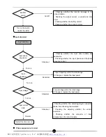
Page 39: ... rectifier switch damage the connection reliable 2 Checking the O P current overload and short circuit 3 Checking charge voltage and current 4 Testing whether contact single normal Cut off 1 Checking whether the bypass switch damage the connect reliable 2 Testing output current overload and short circuit 3 Testing whether the contact normal Cut off 1 Checking whether the output switch damage the c...

Page 40: ...Checking whether the input wires reliable and reasonable 2 Checking whether the input phase and the phase sequence correct Abnormal 1 Input frequency within the rated range 2 Change or replace the input power Abnormal 1 Input voltage within the rated range 2 Change or replace the input power Abnormal 1 Checking whether the sampling single connection reliable Also checking the insulation 2 Checking...

Page 41: ...hether the varistor excursion 3 Checking whether the connector of insert components on the circuit reliable Abnormal Turn on Normal Normal Battery low voltage The wires connection in good condition Battery Charger Restart function recover 1 Cut off battery fasten all fasteners 2 Turn on the battery switch Cut off 1 Battery damage or leakage 2 Battery failure or low capacity 3 Replacement battery A...

Page 42: ...gle connection reliable Also checking the insulation 2 Checking the adjusting whether the varistor excursion 3 Checking whether the connector of insert components on the circuit reliable Abnormal Turn on Normal Normal Output overload Output load Output display date Restart function recover 1 Checking output current or short circuit 2 Reduce the output load Abnormal 1 Cut whether all the power conn...

Page 43: ...re good ventilation conditions 2 Reduce the load reduce the contactor temperature 3 Change the environment temperature Abnormal Normal Normal Transportation failure Communicati on wires Control circuit Restart function recover 1 Checking the connection wires between display board and he main board connection 2 Replacement the connection port Abnormal 1 Checking whether the connection of the MCU in...

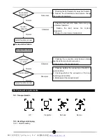
Page 44: ... cord in case of any vibration of the vehicle Although there is anti vibration of the box designed please surely make some anti vibration and drive slowly when in the bumpy road 11 Packing list S N Name Qty piece Notice 1 UPS 1 pc 2 Manual 1 pc Forklift UPS UPS Hook PDF 文件使用 pdfFactory Pro 试用版本创建 www fineprint cn ...

Page 45: ... 6 If can not understand the manual or any more detail please contacted the distributor or our company We will zealously provide our service Notice Any changing of the manual will not be informed specially PDF 文件使用 pdfFactory Pro 试用版本创建 www fineprint cn ...

Reviews: