background image

– 18 –

Manual P5/EP5 23740/98.10

Lower arm

O-rings

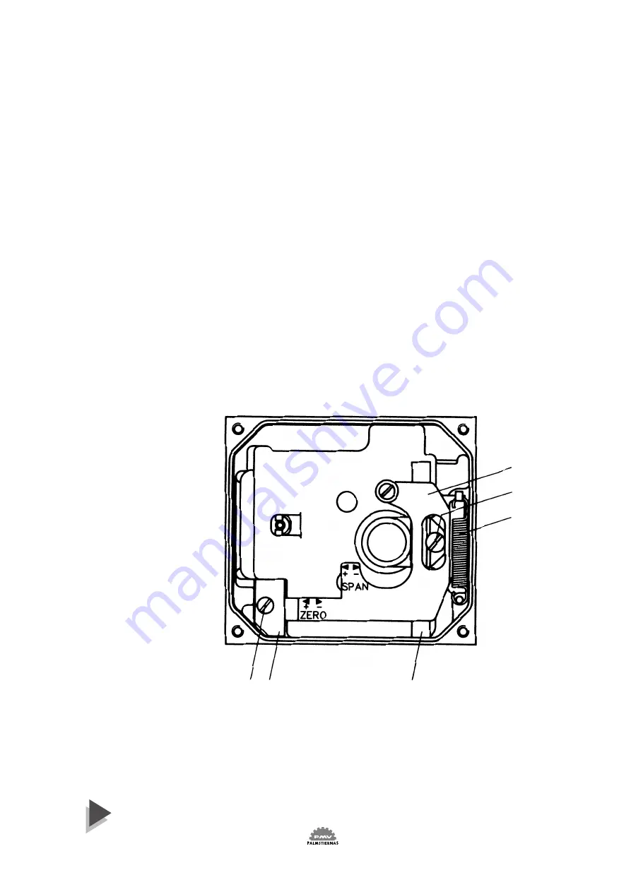
Once the front cover is removed, the lower arm can be easily accessed.
Remove the indicator, feedback spring and the cam.
Loosen screw 2 and remove twist stop 1.
Remove screw 3, lower arm 4, rod 5 and spring 6.
Check rod and lower arm for wear, replace if necessary. Clean the rod
and install it in the lower arm. The lower arm should move easily and
smoothly.
Install the lower arm and rod assembly into the positioner housing,
making sure that the spring 6 is attached properly to the lower arm
and positioner housing.
Secure the lower arm and rod assembly with the screw 3.
Check again that the lower arm moves smoothly.
Apply a small amount of grease on the small tongue on the lower arm,
then install and secure the twist stop.
Install cam, feedback spring, indicator and front cover.

With time and use, O-rings can become brittle. This can cause poor
operation and even failure of the positioner.
Always check O-rings when performing any work on the positioner
and replace bad O-rings.
A thin layer of silicon grease applied on the NBR (Black) O-rings
prolongs their life. On Q (red) O-rings, use a non silicon based grease.

6

 2      1                                                5

4

3

Summary of Contents for EP5

Page 1: ... 1 Manual P5 EP5 23740 98 10 Manual P5 EP5 PMV Valve Control System alve Control System ...

Page 2: ...te entsprechend den gültigen Normen gebaut und zum Einbau in eine Maschine oder Applikation bestimmt sind sowie daß deren Inbetriebnahme so lange untersagt ist bis festgestellt wurde daß diese Maschine Applikation ebenfalls der EG Richtlinie 89 392 EWG und 89 336 EWG entspricht Diese Herstellererklärung hat für folgende PMV Stellungsregler Serien Gültigkeit P5 EP5 F5 F Déclaration de fabricant au ...

Page 3: ...ver 10 7 Span and zero adjustment 11 8 Indicator adjustment 12 9 Cam adjustment 12 10 Dampers 12 11 I P Unit EP5 13 12 How to mount the I P Unit 14 13 Maintenance 15 19 Pilot valve 15 Diaphragm 16 Feedback spring 17 Balance arm 17 Lower arm 18 O rings 18 Filter plug 19 14 Feedback Unit 20 15 Trouble shooting 21 16 Technical Data 21 17 Exploded Drawing 22 18 Spare part list 23 Approvals 24 27 Page ...

Page 4: ...hat can be adjusted to a sealed or drained position The modular design concept allows for easy addition of accessories such as I P converter and or a feedback package both which are isolated from the basic pneumatic unit These accessories can be factory or field mounted Ease of calibration and maintenance are built into to the design with easily accessible span and zero adjustment and very simple ...

Page 5: ...overs which may have loosened in shipment make sure all open enclosure entry points are sealed Feedback modules should have cover tightened and conduits entries sealed Positioners Feedbackmodulesshouldbewrappedandsealedairandwatertightwithdesiccantinside the plastic units should be securely covered with an opaque cover and not exposed to direct sunlight rain or snow Pneumatic positioners Units sho...

Page 6: ...d on Storage Seal or vapour proof tape P5 Remove Storage Seal from connection block mount positioner on actuator valve make connections according to section 5 Page 9 Calibrate span and Zero according to section 7 Page 11 Clean any oil debris off the connecting block then reseal open enclosure entry ports use circularstickersmarkedI SandOUT supplied on Storage Seal or vapour proof tape EP5 Follow P...

Page 7: ...position the complete unit is in a balanced position Air is supplied to the pilot valve through port S and controls the air flow through ports C1 and C2 Assume an equilibrium position An increased control pressure will deflect the diaphragm 1 down compressing the feedback spring 3 The balance arm 2 moves the spool 7 in the pilot valve 8 furnishing supply air to the actuator while at the same time ...

Page 8: ...this stage a review of the pneumatic system should be carried out and the problem corrected Poor air quality is one of the major causes of premature failure of pneumatic equipment P5 mounts on to the actuator using either the ISO F05 holes 4 and a PMV ISO mounting kit or by using the optional mounting adaptor and screws 5 to mount P5 on to existing PMV mounting kits Proper alignment of the positio...

Page 9: ...it Ports Ip P S C1 and C2 are sealed with plugs To install gauges unscrew plugs and replace with gauges We recommend use of tape Loctite 577 or similar user preferred for sealing Port OUT is for venting the unit All air from the positioner actuator and I Punitisventedtoatmospherethrough this port Do not block this port A high flow silencer or an exhaust pipe can be connected to this port to preven...

Page 10: ... unit I P unit and Feedback unit in the PMV Valve Control System P5 This unique sealing system allows for complete sealing or draining of the units by changing the position of the O ring The indicator cover 3 is O ring sealed and secured by a bayonet coupling The indicator cover is also used to secure the identification cover 4 To remove the indicator cover turn it slightly counterclockwise until ...

Page 11: ... Decrease zero span Calibration procedure Check cam seating section 9 before starting calibration procedure 1 Apply 0 input signal 0 20 kPa 3 psi or 4 mA 2 Wait for steady state 3 Adjust zero by turning the silver lower thumb wheel 4 with finger or with screw driver 7 from the outside 4 Apply 100 input signal 100 100 kPa 15 psi or 20 mA 5 Wait for steady state then memorize result 6 Apply 0 input ...

Page 12: ...m 3 as desired making sure that the ball bearing 4 always is riding on an active lobe on the cam To secure the cam make sure that screw 1 is backed out from the locking nut 2 then finger tighten the locking nut and tighten screw 1 Install and adjust the indicator and reinstall cover The standard built in dampers 5 locatedontheconnectingblockprov ide a simple means of adjusting the actuator travel ...

Page 13: ...om the positioner unit Port I on the positioner unit will be plugged when the I P unit and the appropriate gauge block gasket installed The I P unit accepts a 4 20 mA input signal The I P unit is equipped with a built in 30 micron filter Fig 4 Caution Do not operate the unit without filter and filterplug installed Do not unscrew filterplug when the positioner is pressurized Span and Zero for the I...

Page 14: ...e cover on I P unit Install the I P unit to the top of the Positioner unit making sure that the four O rings are present and properly seated Tighten the unit with the three screws See fig 1 and 2 page 13 Screw 1 first screw 2 last WARNING Units installed in hazardous areas must have proper approvals Connect input signal cable to port IE and tighten the cable gland see fig 5 on page 13 Adjust the O...

Page 15: ...20 deg angle the spool should move by itself Should the parts show signs of wear a new assembly is recommended Mixing spool valves and valve bodies may result in very high bleed rates and poor performance Check the O rings then secure and install the pilot valve assembly into positioner unit press it towards the positioner housing wall and secure it with screw 1 Make sure that the leaf spring 4 on...

Page 16: ...oved The diaphragm can after have being in use look wrinkled this is fully normal due to the tension in it When installing the diaphragm make sure to place one washer on each side of the diaphragm Put some Loctite 577 on the thread install the screw 3 and tighten Check the O ring for the diaphragm cover 2 install the O ring into the positioner housing then install cover 2 Secure with screws 1 Torq...

Page 17: ... assembly is aligned properly against the lower arm and the notch is engaged in the tab on the balance arm 2 Balance arm 3 The balance arm can only be removed after I P unit diaphragm and feedback spring have been removed See sections above and on page 13 14 and 16 Loosen the screws 3 and the balance arm can be removed When installing the balance arm make sure that the leafspring 4 on the undersid...

Page 18: ...at the spring 6 is attached properly to the lower arm and positioner housing Secure the lower arm and rod assembly with the screw 3 Check again that the lower arm moves smoothly Apply a small amount of grease on the small tongue on the lower arm then install and secure the twist stop Install cam feedback spring indicator and front cover With time and use O rings can become brittle This can cause p...

Page 19: ...in secondary filter located on the side of the I P unit For replacement or inspection make sure that positioner unit is not pressurized then unscrew filter plug 1 Remove filter 3 and install a new into the filter plug Check condition of O ring 2 and filter compartment If moisture is found check upstream filters oil water separators Moisture can cause I P failure Reinstall filter plug Filter plug 1...

Page 20: ...en be installed on to the Feedback unit WARNING Units installed in hazardous locations must have proper approvals Installing the feedback unit Remove the front cover indicator and Allen head screw from the top of the positioner spindle Install the drive coupling 4 and adjust the O ring seal on the bottom in either sealed or draining position See section 6 page 10 Install the Feedback unit 9 on top...

Page 21: ...t Signal 20 100 kPa 3 15 Psi 6 30 optional 4 20 mA Linearity 0 5 0 5 Hysteresis 0 75 0 5 Repeatability 0 5 0 5 Gain pressure 600 kPa 87 Psi 1 000 kPa kPa Min 66 ISA S75 13 Air consumption at Supply pressure 0 2 MPa 29 Psi 5 4 nl min 0 19 SCFM 6 1 nl min 0 22 SCFM 0 4 MPa 58 Psi 12 3 nl min 0 43 SCFM 13 6 nl min 0 48 SCFM 0 6 MPa 87 Psi 20 nl min 0 71 SCFM 22 nl min 0 78 SCFM 0 8 MPa 116 Psi 27 8 n...

Page 22: ... 22 Manual P5 EP5 23740 98 10 17 Exploded Drawing 98 9 84 ...

Page 23: ... Gasket for P5 6 P5 6EP 1 Gasket for EP5 7 P5 7 1 Diaphragm cover incl O ring 8 P5 8 1 Diaphragm 9 P5 9 2 Diaphragm washer 10 P5 10 1 Balance arm 13 P5 AS13 315 1 Feedback spring 3 15 psi assembly 13 P5 AS13 630 1 Feedback spring 6 30 psi assembly 18 P5 18 1 Lower arm assembly 19 P5 19 1 Rod 20 P5 20 1 Spring 21 P5 21A 1 Indicator Arrow 21 P5 21F 1 Indicator Flag 21 P5 21P 1 Indicator Pointer 22 P...

Page 24: ... 24 Manual P5 EP5 23740 98 10 Approvals E5 IS EU ...

Page 25: ... 25 Manual P5 EP5 23740 98 10 Approvals E5 EX EU ...

Page 26: ... 26 Manual P5 EP5 23740 98 10 Approvals E5 IS US E5 EX US 1 ...

Page 27: ... 27 Manual P5 EP5 23740 98 10 Approvals E5 IS US E5 EX US 2 ...

Page 28: ... any customer modifications to or repair of a certified instrument as this may invalidate the certified design If a certified instrument shoult fail no attempt should be made by the user to effect repair The unit should be returned to the factory WARNING These instruments must be installed in accordance with local and national codes of practice especially for hazardous area installations The instr...

Page 29: ... 29 Manual P5 EP5 23740 98 10 FM ...

Page 30: ... 30 Manual P5 EP5 23740 98 10 CSA ...

Page 31: ... 31 Manual P5 EP5 23740 98 10 CENELEC ...

Page 32: ...V Controls Ltd Headlands Business Park Ringwood Hampshire BH24 3PB ENGLAND Tel 44 0 1425 48 08 88 Fax 44 0 1425 48 08 89 E mail pmv_uk compuserve com Palmstiernas Instrument AB Tulegatan 15 SE 113 53 Stockholm SWEDEN Tel 46 0 8 555 106 00 Fax 46 0 8 555 106 01 E mail info pmvpositioners com Internet www pmvpositioners com The information in this brochure is subject to change without notice PMV USA...

Reviews: