


PMDX-132 User’s Manual
PCB Revision: PCB-466A
Document Revision: 1.0
Serial Numbers: 23410 and above
PMDX-132_Manual_10.doc
©2008 Practical Micro Design, Inc.
Page 8 of 24
17 April 2008
All Rights Reserved
3.0 Functional Description and Block Diagrams
3.1
Data Bus
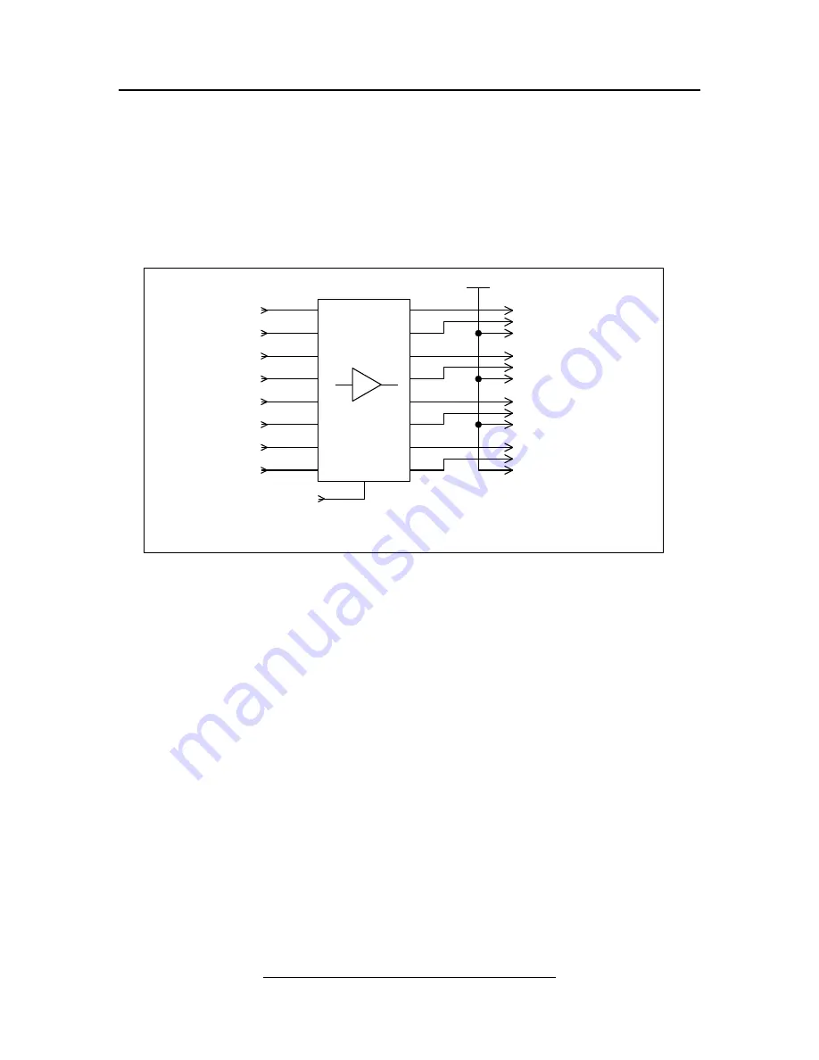
The PC parallel port contains an 8-bit data bus. The PMDX-132 buffers the data bus signals between the
PC and the Gecko stepper drivers. The data bus signals are used as step and direction controls to the
stepper drivers as shown in Table 7 on page 16. The output buffers may be disabled via the
Fault
,
E-Stop
,
or
Motor Disable
inputs, as well the Gecko stepper driver’s “
Error
” output and, optionally, the charge
pump circuit. See sections 3.5 and 3.6 for more information.
Figure 4 – Block diagram of data bus (step and direction) signals
3.2
Control Outputs
The control signals are isolated and buffered by the PMDX-132. Each control signal output has a 10K
ohm pull-down resistor paralleled with an LED. The pull-down resistor provides a default “logic low”
when the output buffer is disabled (due to E-Stop, fault, etc.). The LED lights when the output is driven
or pulled high. Two of the control signals (pin 1and pin 14) may also drive the two relays. See section 3.3
for more information.
Enable
Dir
Step
+5V
PC Connector
Buffer
Common
Gecko #1
OK (isolated)
(from charge pump)
(Data0) pin 2
(Data1) pin 3
(Data2) pin 4
(Data3) pin 5
(Data4) pin 6
(Data5) pin 7
(Data6) pin 8
(Data7) pin 9
Dir
Step
Common
Dir
Step
Common
Dir
Step
Common
All referenced to PC ground
Gecko #2
Gecko #3
Gecko #4


