


PMDX-132 User’s Manual
PCB Revision: PCB-466A
Document Revision: 1.0
Serial Numbers: 23410 and above
PMDX-132_Manual_10.doc
©2008 Practical Micro Design, Inc.
Page 11 of 24
17 April 2008
All Rights Reserved
Condition
(signal asserted)
Step/Dir
Ouputs
Control Outputs
Pin 10 state
(to PC)
Motor Current
(see section 3.5.3)
E-Stop
Disabled
(tri-state)
Disabled
(pull-down resistor)
Logic High
Enabled
Fault
Disabled
(tri-state)
Disabled
(pull-down resistor)
Logic High
Enabled
Gecko Stepper Driver “Error”
Signal
Disabled
(tri-state)
Disabled
(pull-down resistor)
Logic High
Enabled
Motor Disable
Disabled
(tri-state)
Disabled
(pull-down resistor)
Logic High
Disabled
Charge Pump Failure (only when
jumper JP1 is set to “CP-OK”)
Disabled
(tri-state)
Disabled
(pull-down resistor)
Logic Low
Enabled
Table 1 – Summary of effects from fault sources
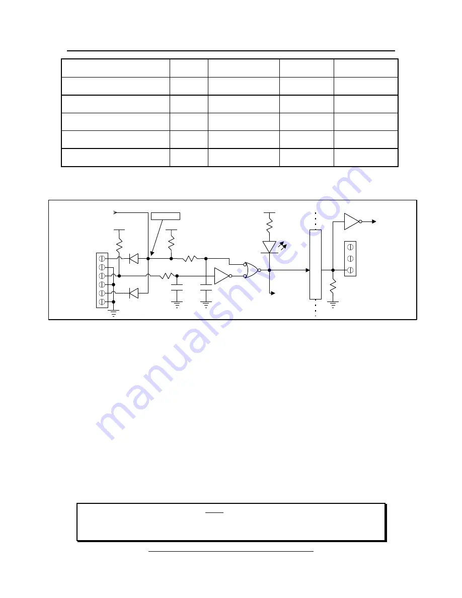
Figure 8 – Block diagram of E-Stop, Fault and Motor Diable signals
3.5.1 Fault Input
The
Fault
input provides an interface for external fault detection circuits. This signal is “active low”,
meaning that a logic “low” indicates a fault condition, and a logic high (or floating) means “all is OK”.
Figure 8 shows block diagrams of the
Fault
input circuitry, and Table 1 on page 11 shows the effects of the
Fault
signal.
The
Fault
input can be connected to an external “wired-or” configuration of open-collector status signals
or mechanical switches to ground (switch closed means “fault”). All of the external fault signals should be
tied together and connected to the PMDX-132’s
Fault
input. The
Fault
input has a 2.2K ohm pull-up
resistor, so the input may be left unconnected when not used. To indicate a fault condition, drive this
input to ground (via either open-collector or TTL-style drivers or mechanical switches).
Some Gecko stepper drivers implement a “fault output” on pin 7. This signal is “wire OR-ed” with the
PMDX-132’s Fault signal so that the Gecko stepper drivers may also signal a fault condition on the
PMDX-132.
NOTE –
The PMDX-132’s
Fault
signal
must
be either driven high (+5V) or allowed to float in
order for the motor driver’s step inputs to be enabled and the pin 10 status signal to
the PC parallel port to go low (signaling “OK”). If you do not have any fault detection
circuitry, leave the
Fault
input unconnected.
J10
Fault*
E-Stop
GND
10K
EStop/Fault
(isolated)
(to status
signal buffer)
2.2K
+5V
+5V
Wired-OR
EStop/Fault*
(active low)
DS10
"EStop Active"
100pF
GND
GND
Gecko
Error
Signals
10K
2.2K
+5V
100pF
I
S
O
L
A
T
E
GND
fan pwr
daisy
2.2K
J5
EStop/Fault*
(to JP1 in the
charge pump)
MotorDisable*


