


PMDX-132 User’s Manual
PCB Revision: PCB-466A
Document Revision: 1.0
Serial Numbers: 23410 and above
PMDX-132_Manual_10.doc
©2008 Practical Micro Design, Inc.
Page 10 of 24
17 April 2008
All Rights Reserved
3.4
Status Inputs
Four of the status signals are available as general-purpose inputs: pins 11, 12, 13 and 15. The fifth status
input on the PC parallel port (pin 10) is connected to the
Fault
and
E-Stop
circuitry. See section 3.5, for
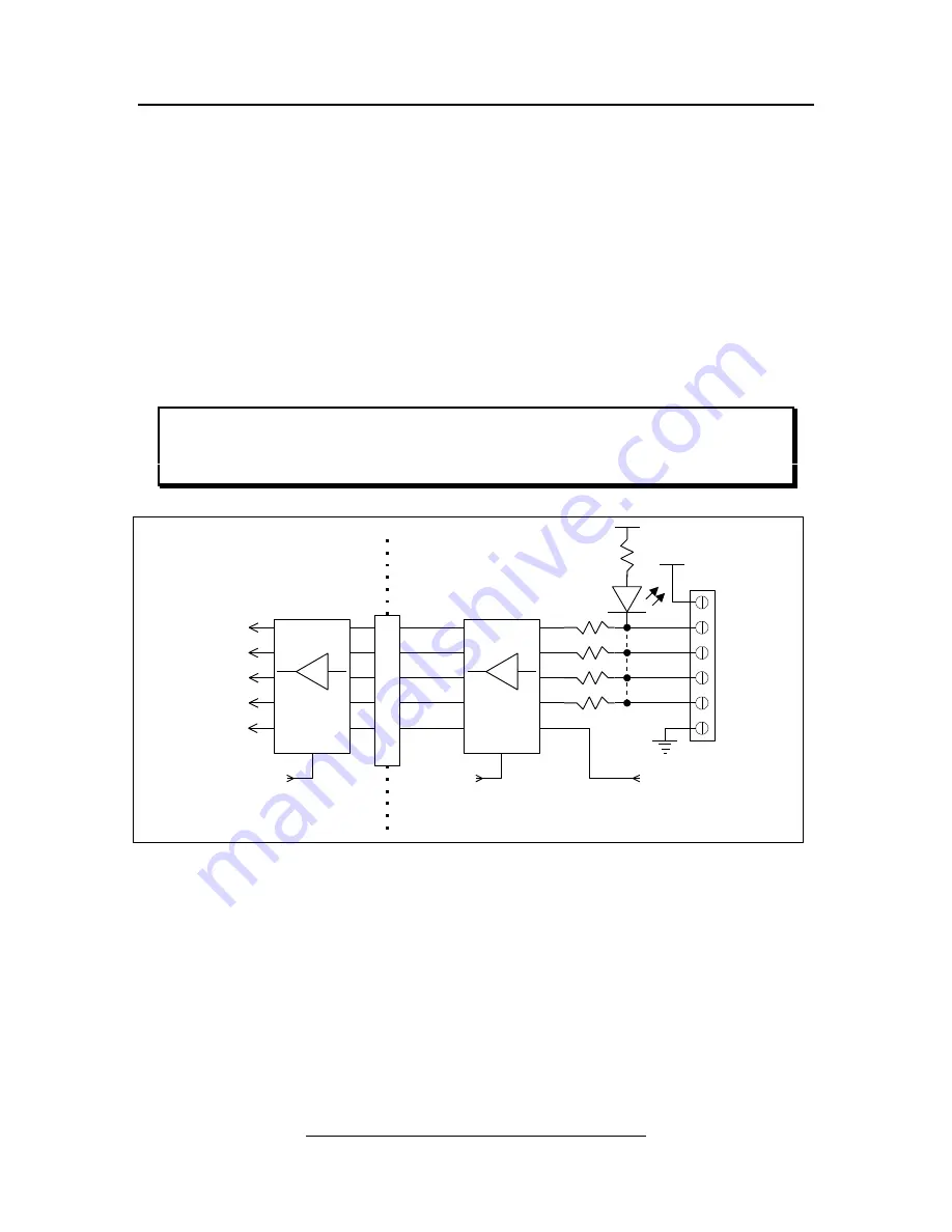
more information on this signal. Figure 7 shows a block diagram of the status input circuitry.
The “Status Input” LEDs are located next to connector J8, just above each of the pin number labels
(“pin 11”, “pin 12”, “pin 13” and “pin 15”). Each LED is “on” when the corresponding input signal is
driven low.
The status signals are isolated and buffered by the PMDX-132. Each status input has a 2.2K ohm pull-up
resistor in series with an LED. The pull-up resistor provides a default “logic high” when the input is not
connected, and also allows the input to be connected to open-collector drivers or mechanical switches to
ground. The LED lights when the input signal is driven low. The optical isolators further act as a low-pass
filter to remove high-frequency noise from the inputs.
NOTE –
Due to logic inside the PC, some status inputs are inverted. This means that a logic
“high” output from the PMDX-132 to the PC’s parallel port is read as a “0” in the
status register. Please refer to technical documentation on the PC parallel port or
your control software for more information.
Figure 7 – Block diagram of status signals
3.5
Fault, E-Stop and Motor Disable
The
Fault
,
E-Stop
and
Motor Disable
inputs, along with the Gecko stepper driver’s “
Error
” signals, provide
ways for external circuitry and the Gecko drivers to enable and disable the operation of the PMDX-132.
The following table summarizes the effects of these signals, as well as the charge pump (see section 3.6).
Figure 8 shows a block diagram of the Fault, E-Stop and Motor Disable circuitry.
**
Each of these four signals have
their own LED and pull-up resistor
Enable
2.2K
PC Connector
Buffer
(~Ack) pin 10
(~Busy) pin 11
(Paper End) pin 12
(Select Out) pin 13
I
S
O
L
A
T
E
Enable
Buffer
10K
J8
+5V
+5V Aux
pin 11
pin 12
pin 13
pin 15
GND
Equipment Ground
PC Ground
(~Error) pin 15
+5V
10K
10K
10K
EStop/Fault (isolated)
(from E-Stop and Fault circuit)
Always
Enabled
Always
Enabled
**
**
**
**


