


PUM_VSR_100209_EN
16/20
0
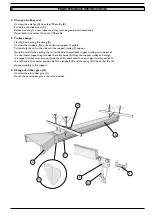
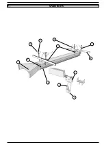
PC-500 MOUNTING PROCEDURE
ELEVATION VIEw
360mm
14,2”
160mm
6,3”
2
1
3
1. VSR profile
2. PC-500, Pressure controller
3. Drilling machine with 10 mm/0.4” drillbit
Drill a 10 mm/0.4” hole in the VSR profile nearby the crab when
the vehicle is in its rest position.
Thread the pressure controller directly into the VSR profile.
Mount a pressure controller the same way at the end of the exit
side on the rail, to achieve fan start when the vehicle returns.
Connect the electrical low voltage cables to the pressure
controller with accompanying tags.
Further connection to pressure control unit, PCU-1000,
see separate electrical diagram.
2
7.
MOUNTING INSTRUCTION


