background image

E – 2

Installation

* Allow at least 10 cm (3.9 inch) of space between the projector top

panel and its surroundings.
Also allow at least 10 cm (3.9 inch) of other spaces around the pro-
jector.

* The projector should be placed on a flat, level surface and in a dry

area free from dust and moisture.

* The projector should always be handled with care. Dropping or jar-

ring the projector could damage internal components.

* If you wish to have the projector installed on the ceiling do not attempt

to install the projector yourself. The projector must be installed in ac-
cordance with any local building codes by qualified technicians in or-
der to ensure proper operation and reduce the risk of bodily injury.

* Do not place this product near water, near a bathtub, in a wet base-

ment or near a swimming pool and the like.

Power supply

* The projector is designed to operate on a power supply of 100-240V AC,

50/60Hz. Ensure that your power supply fits this requirement before at-
tempting to use your projector.

* Handle the power cable carefully and avoid excessive bending. A

damaged cord can cause electric shock or fire.

* If the projector is not be used for an extended period of time, discon-

nect the plug from the power outlet. Do not unplug the power cable
from the wall outlet under the following circumstances, doing so may
cause damage to the projector:

Cleaning

* Unplug the projector before cleaning.
* Use a blower or lens paper to clean the lens, and be careful not to

scratch or mar the lens.

Lamp Replacement

Be sure to replace the lamp when the message "Replace The Lamp"
appears on the screen. If you continue to use the lamp after 1100
hours of usage, the lamp will not turn on. To replace the lamp, follow all
instructions on page E-46.

Fire and Shock Precautions

* The openings should never be covered or blocked by placing the

product on a bed, sofa, rug, or other similar surface.

* Prevent foreign objects such as paper clips and bits of paper from

falling into the projector. Do not attempt to retrieve any objects that
fell into the projector.

* Do not insert any metal objects such as a wire or screwdriver into

the projector. If something should fall into the projector, immediately
disconnect the power cord from the projector and have the object
removed by a qualified service person.

* Do not place any liquids on top of the projector.

Do not look into the lens while the projector is on. Serious dam-
age to your eyes could result.

Important Safety Information

CAUTION

CAUTION: 

TO REDUCE THE RISK OF ELECTRIC SHOCK, DO

NOT REMOVE COVER. NO USER-SERVICEABLE PARTS INSIDE.
REFER SERVICING TO QUALIFIED SERVICE PERSONNEL.

This symbol warns the user that uninsulated voltage
within the unit may have sufficient magnitude to cause
electric shock. Therefore, it is dangerous to make any
kind of contact with any part inside of this unit.

This symbol alerts the user that important literature con-
cerning the operation and maintenance of this unit has
been included. Therefore, it should be read carefully in
order to avoid any problems.

The above cautions are given on the bottom of the product.

CAUTION

To turn off main power, be sure to remove the plug from
the power outlet.
The power outlet socket should be installed as near to the
equipment as possible, and should be easily accessible.

WARNING

TO  PREVENT FIRE OR SHOCK HAZARDS, DO NOT
EXPOSE THIS UNIT TO RAIN OR MOISTURE. ALSO DO
NOT USE THIS UNIT'S POLARIZED PLUG WITH AN EX-
TENSION CORD RECEPTACLE OR OTHER OUTLETS,
UNLESS THE PRONGS CAN BE FULLY INSERTED. RE-
FRAIN FROM OPENING THE CABINET AS THERE ARE
HIGH-VOLTAGE COMPONENTS INSIDE. REFER SER-
VICING TO QUALIFIED SERVICE PERSONNEL.

DOC compliance Notice

This Class B digital apparatus meets all requirements of the Canadian
Interference-Causing Equipment Regulations.

WARNING

This equipment has been tested and found to comply with the limits for
a Class B digital device, pursuant to Part 15 of the FCC Rules. These
limits are designed to provide reasonable protection against harmful
interference in a residential installation. This equipment generates, uses
and can radiate radio frequency energy and, if not installed and used
in accordance with the instructions, may cause harmful interference to
radio communications. However, there is no guarantee that interfer-
ence will not occur in a particular installation. If this equipment does
cause harmful interference to radio or television reception, which can
be determined by turning the equipment off and on, the user is encour-
aged to try to correct the interference by one or more of the following
measures:
• Reorientate or relocate the receiving antenna.
• Increase the separation between the equipment and receiver.
• Connect the equipment into an outlet on a circuit different from that

to which the receiver is connected.

• Consult the dealer or an experienced radio/TV technician for help.

RISK OF ELECTRIC SHOCK
DO NOT REMOVE SCREWS
EXCEPT SPECIFIED USER
SERVICE SCREW.

Please read this manual carefully before using the projector and keep
the manual handy for future reference.

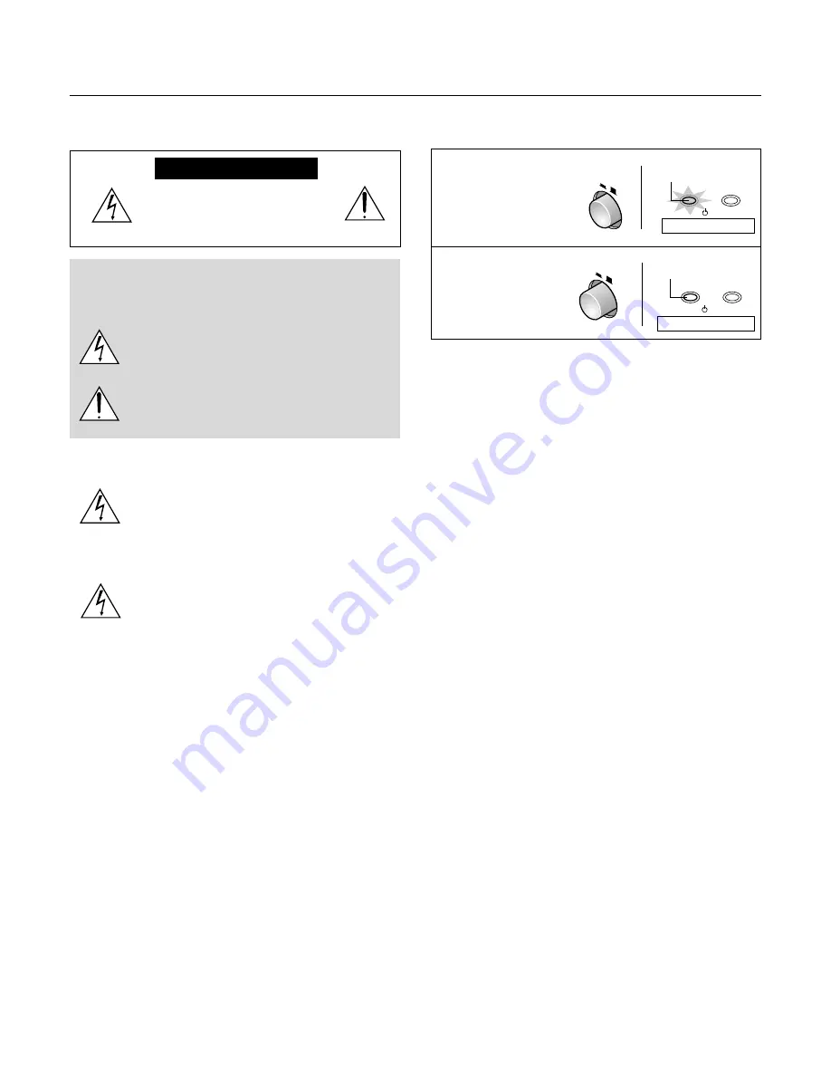
POWER

ON

OFF

STATUS

POWER /

POWER

ON

OFF

POWER /

STATUS

Main power ON

Main power OFF

Turning ON or OFF Main Power

Make all hookups before turning on the main power.

To turn on the main power:

Press the POWER
switch down until it is in
the depressed position.

To turn off the main power:

Press the POWER
switch until it is in the
protruded position.

On condition

Off condition

Light in orange

Indicator OFF

Summary of Contents for PLUS Piano HE-3200

Page 1: ...User s Manual HE 3200 English...

Page 2: ...ol warns the user that uninsulated voltage within the unit may have sufficient magnitude to cause electric shock Therefore it is dangerous to make any kind of contact with any part inside of this unit...

Page 3: ...ype plug has two blades and a third grounding prong The wide blade or the third prong are provided for your safety If the provided plug does not fit into your outlet consult an electrician for replace...

Page 4: ...n t interfere with the enjoyment of movie watching in an indoor environment Installation Flexibility The compact design of about B5 paper size 182 x 257 mm 7 2 x 10 1 inch and mere 2 kg 4 4 lbs weight...

Page 5: ...n Screen Menu E 28 Menu List E 31 Video Adjustments Picture 1 E 33 Adjusting the Brightness E 33 Adjusting the Contrast E 33 Adjusting the color E 33 Adjusting the tint E 34 Adjusting the Sharpness E...

Page 6: ...m 5 9 feet This power cord supplies power to the unit See Page E 16 about connections S Video cable 3 m 9 8 feet No 771709100 This cable is used when the output connector of the equipment to be conne...

Page 7: ...Page E 16 POWER STATUS ON STANDBY ASPECT SOURCE POWER STANDBY indicator On and Standby operation modes are indicated when this indicator is flashing green or lit orange The indicator is not lit when t...

Page 8: ...tput connector of the equipment to be connected Page E 19 RGB Connector This is connected with the RGB output connector mini D Sub 15 pin of the equipment to be connected Page E 17 YPbPr YCbCr Connect...

Page 9: ...s are bonded Being carful not to mar the plastic part of the front feet remove the rubber pads 2 After putting projections on the back of the supplied adjuster into depressions of the front feet tight...

Page 10: ...ON the power and set the unit to the STANDBY mode Page E 21 These buttons are used for menu opera tions Page E 28 Using the On Screen Menu MENU button This is used in the selection of the menu name w...

Page 11: ...ol Range Point the remote control toward the remote control sensor located at the rear of the main unit and operate The range over which the main unit will receive the remote control signal is roughly...

Page 12: ...ing the vertical and horizontal aspect of the picture i e the ratio of screen width and height Page E 23 27 Selection of Aspect Ratio i e Ratio of Screen Width to Screen Height 1 2 3 4 5 6 7 8 9 Note...

Page 13: ...ould be out side the zoom adjustment range and a test projec tion should be conducted Page E 24 Input Screen and Aspect Ratio Selection Screen 160 0 wide x 120 0 high inch 200 inch 406 4 wide x 304 8...

Page 14: ...high cm Screen Size 130 7 wide x 73 5 high inch 150 inch 331 6 wide x 187 7 high cm 104 5 wide x 58 8 high inch 120 inch 265 3 wide x 150 1 high cm 87 1 wide x 49 0 high inch 100 inch 221 1 wide x 12...

Page 15: ...ical dimension H dimension 7 2 cm 2 8 inch Screen size top edge dimension measured from floor Lens center Stand dimension Note Determine the screen size after checking the height and width of the room...

Page 16: ...the projector as near to the power outlet socket that is easily accessible Do not switch off the main power or disconnect the power cable unless the POWER indicator is lit orange Doing so could shorte...

Page 17: ...DV I D RG B CT RL S VIDE O VIDE O Y Pb Cb Pr Cr RGB S VIDEO VIDEO Y Pb Cb Pr Cr VIDEO VIDEO AUDIO R L S VIDEO VIDEO AUDIO R L Connections with the Video Output Connector Connect to the green jack Vide...

Page 18: ...7 062 Make connections to the YCbCr output jacks marked COMPONENT or COLOR DIFFERENCE SIGNAL The YPbPr YCbCr connectors and the cables are color coded Match the same colors when making connections Not...

Page 19: ...nal computer side Check with the Table of Supported Frequencies on Page E 49 The setting method of the personal computer will vary depending on your personal computer For information read the instruc...

Page 20: ...m the notebook computer please try the operation described below For an IBM PC AT DOS V computer press the Fn key plus any one of the F1 to F12 keys See the table below Manufacturer Model Key akia All...

Page 21: ...ds Note When the unit is set to off and the LED is not lit using the menu Setup LED items the indicator flashes green for 60 seconds then goes off Setting standby mode Press and hold down the ON STAND...

Page 22: ...rated in the diagram is the result of the projector not being perpendicular to the screen Set the projector so that it is pointing straight toward the screen 4 If the image shows keystone distortion a...

Page 23: ...e display see Page E 41 On Screen Display Duration Setting This completes the projection screen adjustments Note The remote control provides direct selec tion from the VIDEO button S VIDEO but ton YCb...

Page 24: ...ntains a video image aspect ratio of 4 3 and projects it Images with a 16 9 aspect ratio will become vertically elongated 4 3 Select Thru This projects the input image as is When the input resolution...

Page 25: ...R button of the main unit and turn on the main power To turn on the power Check that the POWER indicator of the main unit is lit or ange Press the ON STANDBY button for about 2 seconds The power will...

Page 26: ...e cursor button or the VIDEO YPbPr button A press of the SET button causes the source selection display to disappear performs a search for the specified signal and projects it Note When the power is s...

Page 27: ...ent Match the aspect ratio of the image of the connected equipment with the aspect ratio of the projected image of this unit or ad just the image of a 16 9 aspect to the de sired format When the aspec...

Page 28: ...ts selection Picture1 Language En De Fr It Es Menu Position Duration 10 sec Picture2 Setup Info VIDEO Option Names and functions of the menu screens Menu names These are the menu headings When a menu...

Page 29: ...djustment or selection Adjust or select to produce the best picture Making Adjustments and Settings Picture1 Keystone Mode Normal Full Blue Black 0 Keystone Off On Off On Installation Background Auto...

Page 30: ...the sub menu depending on the item contents Note A transition to item selection of the menu will not be possible while the sub menu is being displayed To select the next item press the ESC button clos...

Page 31: ...stom Picture2 Setup Info VIDEO Option Picture1 Brightness 0 Contrast 0 Color 0 Sharpness 2 Color Temp Low Normal High Custom Picture2 Setup Info YCbCr Option Picture 2 Picture1 Video Filter 2 3 Zoom F...

Page 32: ...up Info DVI Option VIDEO Menu List Viewing the Lamp Timer Resolution and Frequency Page E 43 RGB and DVI Input Selection Setup Picture1 Keystone Mode Normal Full Blue Black 0 Keystone Off On Off On In...

Page 33: ...djust with the cursor button Cursor Button Lighter color Cursor Button Deeper color Picture1 Brightness 0 0 Contrast 0 Color Tint 0 Sharpness 1 Color Temp Low Normal High Custom Picture2 Setup Info VI...

Page 34: ...ght The color temperature adjustment serves to adjust the proportions of this mixture The color representation on the screen will change depending on the environ ment including room illumination Custo...

Page 35: ...l and the pixel position of the projec tor This is adjusted by the adjust ment of the clock frequency When the image extends beyond the screen or is smaller than the screen check whether the Aspect se...

Page 36: ...the picture at the time of pixel conversion in the selection of the aspect ratio Press the cursor button and align the cursor with the desired item then adjust with the cursor but ton Adjust to your...

Page 37: ...e cursor button and align the cursor with the index 2 Select the adjustment point with the cursor but ton 3 Select the color that is to be adjusted with the cursor button then adjust with the cursor b...

Page 38: ...on display will appear Press the cursor button to match the format of the input signal then press the SET button to finalize Picture1 Zoom Filter Gamma Format Auto Color Space Picture2 Setup Info YPbP...

Page 39: ...en is in clined which results in a difference in the distance of upper and lower projection points Keystone cor rection compensates for this This projector has two correction modes Installation Screen...

Page 40: ...ring projection in a dark room Press the cursor button and align the cursor with LED then make the selection with the cursor button Off Switches off the LED On Lights the LED Note The projector will a...

Page 41: ...This function changes the display position of the on screen menu Press the cursor button and align the cursor with Menu Position then press the SET button and the display will change to the menu posi...

Page 42: ...ment and setting val ues of the current input mode Loading 1 Project the image that you want to save 2 Press the cursor button and align the cursor with User Memory then press the cursor button and se...

Page 43: ...mer Reset Status 100 500 Lamp Timer 1 hrs Total 1 hrs Picture2 Setup Info Option VIDEO Lamp Timer Reset No Yes Note Items that cannot be speci fied for each input will be returned to the initial setti...

Page 44: ...tion of your personal computer At the time of RGB input is the clock frequency correct or shifted a little At the time of YPbPr input does the format setting match the input signal or is it different...

Page 45: ...h on the power again If the unit still does not operate consult your dealer POWER ON STANDBY STATUS The faults described below are being indicated when the indicators of the projector control panel ar...

Page 46: ...about 60 minutes for the lamp cartridge to cool before replacing Wait at least 60 minutes for the lamp cartridge to cool DO NOT TOUCH THE LAMP CARTRIDGE immediately after it has been used It will be...

Page 47: ...zero From the menu select Info Lamp Timer Reset and then reset the lamp usage hours See Resetting the Lamp Timer on page E 43 NOTE When the projector lamp has exceeded 1100 hours of operation the pro...

Page 48: ...the internal temperature to rise which could cause damage Clean this area carefully As a guideline clean at least every 100 hours Cleaning Attention Be certain to disconnect the power plug from the p...

Page 49: ...00 x 600 35 2 56 3 800 x 600 37 9 60 3 800 x 600 46 9 75 0 800 x 600 48 1 72 2 800 x 600 53 7 85 1 1024 x 768 48 4 60 0 1024 x 768 56 5 70 1 1024 x 768 57 7 72 0 1024 x 768 60 0 75 0 1024 x 768 68 7 8...

Page 50: ...ive Negative Input Terminal RGB Mini D Sub 15 pin RGB Signal VGA 640 480 Throughput image Magnified image S VGA 800 600 Throughput image XGA 1024 768 Throughput image Compressed image Video Input Comp...

Page 51: ...E 51 Main Unit External View DVI D RGB S VIDEO VIDEO Y Pb Cb Pr Cr 91 mm 3 6 inch 235 mm 9 3 inch 174 mm 6 9 inch 198 mm 7 8 inch...

Reviews: