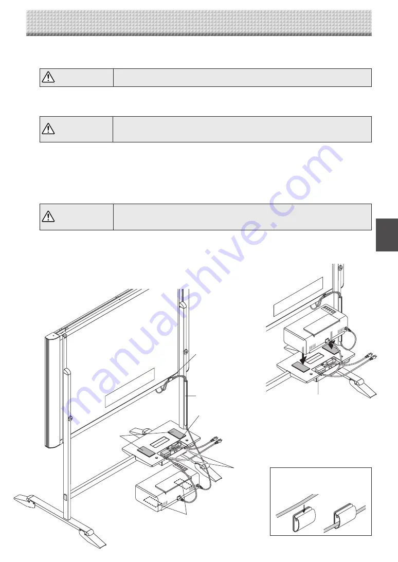
Plus N-20 Series Assembly And Setup Manual Download Page 8

E-7

Rear surface

Cable cover

Cable hole

Velcro 

Velcro 

Main unit's AC power adapter
Printer's AC power adapter

Cable clip

Using the cable clip

Fasten the cables with the cable 

clip.

 4. Assembly of the Stand 

AC power adapter box

Rear surface

4

.  Store the AC power adapters and cables in the AC power adapter box.

Connect the main unit and printer before storing the adapters and cables. (See page E-14.)

CAUTION

•  Check that the AC power plug is not connected to a wall power outlet. If it is, be sure 

to unplug it.

The shorter side of the T-shaped foot is the back of the stand. The diagrams show the procedure from the back side.

  Put the AC power adapters of the main unit and printer in the AC power adapter box.

WARNING

•  The AC power adapters and the power cords generate heat. Be sure to wire them in 

such a way that they keep apart. Do not bundle the cables together. Doing so could 
cause them to heat up, leading to fire.

  Fasten the cables with the cable clip, then insert them in the cable cover.

  Put the cables into the AC adapter box's cable hole. (The cables enter when pushed in.)

  Peel the backing sheet of the Velcro and attach the Velcro to the bottom of the printer and the printer table. Fasten 

the Velcro on the printer table in a position opposite the position on which the Velcro is attached on the printer. 

Also, do not attach the Velcro to a sunken part of the printer, or it will not touch the Velcro on the printer table.

CAUTION

•  The Velcro is attached to prevent slipping. It is not strong enough to prevent falling. 

Remove the printer when moving the stand. If not, the printer could be damaged or fall 
on your feet, etc., causing injury.

  Place the printer on the printer table.

•  Place any extra cable length in the AC power adapter box so that no cable is hanging out.

This completes mounting of the main unit on the stand. Make a test print.

See page E-15.

Summary of Contents for N-20 Series

Page 1: ...N 20 N 20 Series Copyboard Assembly and Setup Manual English...

Page 2: ...ssembly of the stand E 5 5 Wall Mounting E 8 6 Connecting the Cables With the Main Unit Connections Diagram E 14 7 Test Print E 15 To the Customer Special skills are required to install the set Never...

Page 3: ...post in the wall or a sturdy wall stud When the mounting positions of the main unit are not reached please use optional wall support fittings Please use hardware like anchor nuts and anchor bolts for...

Page 4: ...h power cord Dedicated markers 4 One each of black red blue and green Dedicated eraser 1 with 2 spare sponges USB cable 1 User s manual 1 Assembly and Setup Manual this manual 1 Important Safety Infor...

Page 5: ...tray s screw holes and slide downwards as such to slip the pen tray into place Tighten the screws The method of installation differs according to the installation type When installed on the stand 4 As...

Page 6: ...rew and Plain washer into the sleeve then use the hexagonal wrench to partially fasten it to the side bar Check that the sleeve is not sticking out Once mounting of the left and right T shaped feet is...

Page 7: ...ily injury or damage the machine Alignment of the screw holes of the T shape feet with those of the stabilizers Slide the stabilizers on the T shaped feet to align with the holes CAUTION Do not lift t...

Page 8: ...Do not bundle the cables together Doing so could cause them to heat up leading to fire Fasten the cables with the cable clip then insert them in the cable cover Put the cables into the AC adapter box...

Page 9: ...ter of the bottom fixing bracket threaded hole Center of the top fixing bracket threaded hole standard type 1480 unit shape wide type 1980 unit shape 27 27 995 unit shape 70 70 Side board ex Stud Colu...

Page 10: ...teel wall is reinforced and use a drill a hole of suit able diameter then attach the main unit with tapping screws Reference Installation Method for Various Wall Materials Please perform an installati...

Page 11: ...ON Insert the unit in the top wall brackets with at least 2 people If the unit comes out of place it may fall and cause injury After mounting the unit in the top wall brackets hold the top of the unit...

Page 12: ...e than 5 kg Place the wall printer table at the position in which it is to be mounted then insert a gimlet or other pointed object accurately through the center of the screw holes to mark the wall sur...

Page 13: ...USB cable There is a cable hole on the wall side of the printer table Pass the DC cable of the main unit s AC power adapter and the printer s AC power cable through the printer table s cable hole bef...

Page 14: ...not bundle the cables together Doing so could cause them to heat up leading to fire Put the cables in the notches top and bottom on the left side of the AC power adapter box and attach the AC power a...

Page 15: ...lled on the stand See page E 5 When installed on a wall See page E 8 Main unit front To DC INPUT connector To DC connector To Printer connector To USB connector Printer USB cable supplied with the pri...

Page 16: ...er 4 Open the top cover and open the paper tray 5 Set A4 or letter size paper 6 Write or draw a diagram on the sheet surface 7 Press the color print button for a color print the black and white print...

Page 17: ...26 4607 11B...

Reviews: