Plus N-20 Series Assembly And Setup Manual Download Page 15

E-14

6. CONNECTING THE CABLES WITH THE MAIN UNIT

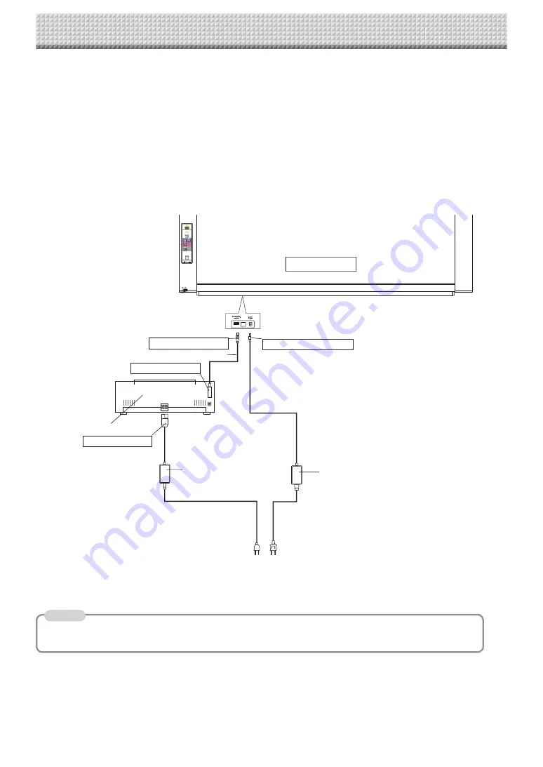
 (CONNECTIONS DIAGRAM)

Connect as shown on the diagram below. Do not connect the AC power adapters' AC power plugs to the wall 
power outlet yet.
Once connections are completed, store the AC power adapters and cables in the AC power adapter box. The 
way this is done differs depending on whether the main unit is installed on the stand or the wall.
 

When installed on the stand: See page E-5.


When installed on a wall: See page E-8.

Main unit front

To DC INPUT connector 

To DC  connector 

To Printer connector 

To USB connector 

Printer

USB cable (supplied with the printer)

AC power adapter (supplied)

Printer AC power adapter
 (supplied with the printer)

To wall power outlet

[Copyboard and Printer Connections Diagram]

The AC power adapters of accessories and printers that have been verifi ed to be operation many differ from the ones 
shown on the connections diagram (they may be of the built-in or mounted-on type).

Note

* Appearance of printer is for illustration purposes.

Summary of Contents for N-20 Series

Page 1: ...N 20 N 20 Series Copyboard Assembly and Setup Manual English...

Page 2: ...ssembly of the stand E 5 5 Wall Mounting E 8 6 Connecting the Cables With the Main Unit Connections Diagram E 14 7 Test Print E 15 To the Customer Special skills are required to install the set Never...

Page 3: ...post in the wall or a sturdy wall stud When the mounting positions of the main unit are not reached please use optional wall support fittings Please use hardware like anchor nuts and anchor bolts for...

Page 4: ...h power cord Dedicated markers 4 One each of black red blue and green Dedicated eraser 1 with 2 spare sponges USB cable 1 User s manual 1 Assembly and Setup Manual this manual 1 Important Safety Infor...

Page 5: ...tray s screw holes and slide downwards as such to slip the pen tray into place Tighten the screws The method of installation differs according to the installation type When installed on the stand 4 As...

Page 6: ...rew and Plain washer into the sleeve then use the hexagonal wrench to partially fasten it to the side bar Check that the sleeve is not sticking out Once mounting of the left and right T shaped feet is...

Page 7: ...ily injury or damage the machine Alignment of the screw holes of the T shape feet with those of the stabilizers Slide the stabilizers on the T shaped feet to align with the holes CAUTION Do not lift t...

Page 8: ...Do not bundle the cables together Doing so could cause them to heat up leading to fire Fasten the cables with the cable clip then insert them in the cable cover Put the cables into the AC adapter box...

Page 9: ...ter of the bottom fixing bracket threaded hole Center of the top fixing bracket threaded hole standard type 1480 unit shape wide type 1980 unit shape 27 27 995 unit shape 70 70 Side board ex Stud Colu...

Page 10: ...teel wall is reinforced and use a drill a hole of suit able diameter then attach the main unit with tapping screws Reference Installation Method for Various Wall Materials Please perform an installati...

Page 11: ...ON Insert the unit in the top wall brackets with at least 2 people If the unit comes out of place it may fall and cause injury After mounting the unit in the top wall brackets hold the top of the unit...

Page 12: ...e than 5 kg Place the wall printer table at the position in which it is to be mounted then insert a gimlet or other pointed object accurately through the center of the screw holes to mark the wall sur...

Page 13: ...USB cable There is a cable hole on the wall side of the printer table Pass the DC cable of the main unit s AC power adapter and the printer s AC power cable through the printer table s cable hole bef...

Page 14: ...not bundle the cables together Doing so could cause them to heat up leading to fire Put the cables in the notches top and bottom on the left side of the AC power adapter box and attach the AC power a...

Page 15: ...lled on the stand See page E 5 When installed on a wall See page E 8 Main unit front To DC INPUT connector To DC connector To Printer connector To USB connector Printer USB cable supplied with the pri...

Page 16: ...er 4 Open the top cover and open the paper tray 5 Set A4 or letter size paper 6 Write or draw a diagram on the sheet surface 7 Press the color print button for a color print the black and white print...

Page 17: ...26 4607 11B...

Reviews: