background image

26 


12.9


Connection of temperature 

sensors 

Regulator works with sensors - type CT4 and 
CT2S  only.  Use  of  other  sensors  is  not 
allowed. 
Sensor wires may be extended using wires of 
cross-section  area  not  less  than  0,5mm

2

Total  length  of  wires  of  each  sensor  should 
not exceed 15m.   
Insert  boiler  temperature  sensor  into 
thermometer  well  fastened  to  boiler  shell. 
Fasten  feeder  temperature  sensor  to  the 
surface  of  feeder  screw  tube.  Insert 
temperature  sensor  of  HUW  container  into 
thermometer  well  welded  to  the  container. 
The  best  way  to  mount  mixer  temperature 
sensor is to insert it into a sleeve located in 
the  stream  of  flowing  water,  however,  it  is 
also allowed to fasten the sensor in a contact 
manner  provided  that  the  sensor  and  the 
pipe are properly heat-insulated. 


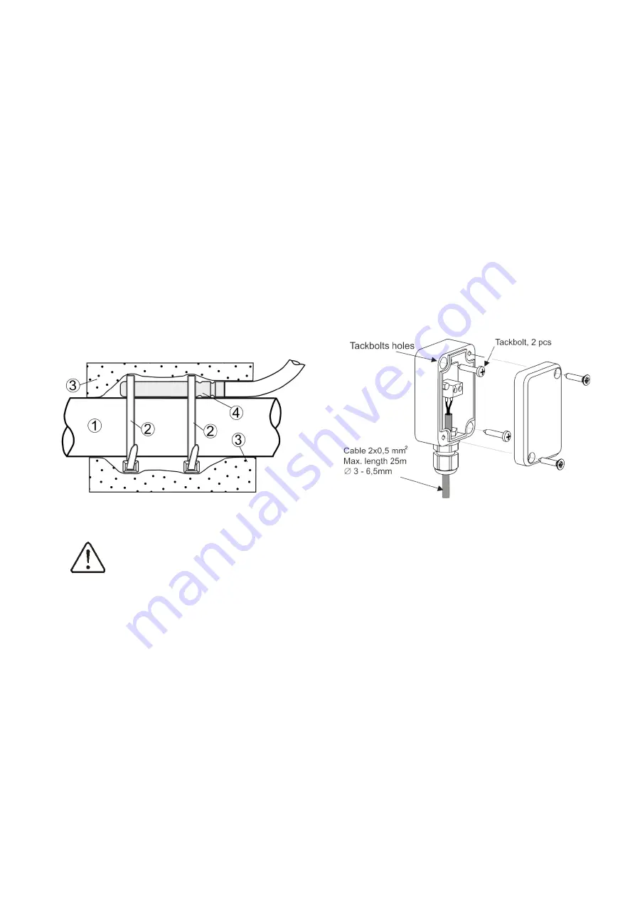
Mounting  temperature  sensor:  1  -  pipe,  2  – 
clamps,  3  -  thermal  insulation,  4  -    temperature 
sensor.


Sensors shall be protected against 
loosening  from  surfaces  they  are 
mounted to. 

Make  sure  thermal  contact  between  the 
sensors and the surface which temperature is 
measured  is  good.  Apply  thermal  paste  to 
improve the contact. Pouring sensors with oil 
or water is not allowed.  
Sensor  wires  should  be  separated  from 
power  supply  wires.  Otherwise,  temperature 
indications  may  be  erroneous.  Min.  distance 
between these wires should be 100mm.  
Do  not  allow  sensor  wires  to  contact  hot 
parts of the boiler and heating system. Wires 
of temperature sensors are heat resistant to 
the temperature not exceeding 100°C.  

12.10


Connection of weather sensor 

Regulator  works  with  weather  sensors  type 
CT6-P  only.  Fasten  the  weather  sensor  on 
the coldest wall of the building - usually it is 
a  roofed  area  of  north  wall.  The  sensor 
should  not  be  exposed  to  direct  sunlight  or 
rainfall.  Install  the  sensor  at  the  height  of 
min.  2m  above  ground  level  in  the  location 
away  from  windows,  chimneys  and  other 
heat 

sources, 

which 

may 

interfere 

temperature  measurements  (min.  distance: 
1,5m). 
Use  cable  of  wire  with  cross  section  area  of 
min.  0,5mm

2

  and  length  of  up-to  25m  to 

connect  the  sensor.  Wire  polarization  is 
irrelevant.  Connect  other  cable  end  to 
regulator terminals. 
Bolt  the  sensor  to  the  wall  using  erection 
bolts.  Holes  for  bolts  are  accessible  upon 
removal of sensor housing lid. 


12.11


Connecting exhaust sensor 

The  exhaust  sensor  should  be  fitted  in  the 
boiler flue. The gap between the sensor and 
the flue should be sealed. The sensor should 
be  installed  by  a  qualified  fitter,  while 
observing  regulations  applicable  for  chimney 
systems.  The  emission  sensor  should  be 
connected  to  the  sensor  terminals  acc.  to 
The  emission  sensor  lead  cannot  touch  hot 
elements  of  the  boiler  and  the  flue,  the 
temperature  of  which  exceeds  350°C.  The 
emission  sensor  should  be  installed  in  such 
distance  from  the  boiler  at  which  it  is  not 
directly  exposed  to  flames,  and  where  the 
emission  temperature  does  not  exceed 
450°C. 

Summary of Contents for ecoMAX860P3-LZ

Page 1: ...LZ FOR PELLET BOILERS 10 2018 ecoSTER TOUCH ecoNET300 ecoNET apk ecoNET app www econet24 com ecoSTER200 room panel ecoSTER TOUCH or ecoSTER200 and ecoNET300 internet module isn t the standard equipment of the regulator functions available in the additional module B ...

Page 2: ...tallation etc check if the regulator is not connected to the mains Installation should be done by a person with appropriate electrical qualifications Improper cables connection could result in the regulator damage The regulator cannot be used in steam condensation conditions and cannot be exposed to water ...

Page 3: ...12 4 ASSEMBLY OF MODULE 22 12 5 IP RATING 23 12 6 ELECTRIC CONNECTION 23 12 7 PROTECTIVE CONNECTIONS 23 12 8 ELECTRIC SCHEME 24 12 9 CONNECTION OF TEMPERATURE SENSORS 26 12 10 CONNECTION OF WEATHER SENSOR 26 12 11 CONNECTING EXHAUST SENSOR 26 12 12 CHECKING OF TEMPERATURE SENSORS 27 12 13 CONNECTION OF MIXERS ROOM THERMOSTAT 27 12 14 CONNECTION OF RESERVE BOILER 27 12 15 CONNECTION OF ALARM SIGNAL...

Page 4: ...egulator a boiler manufacturer should check if the regulator s mating with the given boiler type is proper and whether it can cause danger The regulator is not an intrinsically safe device which means that in the case of malfunction it can be the source of a spark or high temperature which in the presence of flammable dusts or liquids can cause fire or explosion Thus the regulator should be separa...

Page 5: ... hence the user should read both parts of the manual We are not responsible for any damages caused by failure to observe these instructions 4 Storage of documentation This assembly and operation manual as well as any other applicable documentation should be stored diligently so that it was available at any time In the case of removal or sale of the device the attached documentation should be hande...

Page 6: ...6 ...

Page 7: ...INSTRUCTION MANUAL ecoMAX860P3 LZ ...

Page 8: ...MER mode Winter Summer Auto Act temp SUMMER Deact Temp SUMMER Mixer 1 4 settings Preset mixer temp Mixer room therm Mixer out temp dep Mixer heating curve Curve shift Room temp factor Night time decrease Boiler Night time decrease Schedule Mixer 1 4 Night time decrease Decrease Schedule HUW container Night time decrease Decrease Schedule Circulation pump Night time decrease Decrease Schedule Gener...

Page 9: ...perature increase to load the buffer 5 symbol signalling fan operation 6 symbol signalling main feeder operation 7 symbol signalling central heating CH pump operation 8 symbol signalling central heating pump operation HUW 9 measured temperature of hot water boiler HUW 10 preset hot water HUW boiler temperature 11 clock and weekday 12 Part of the screen coshared between two icons match symbolizes o...

Page 10: ...the exhaust temperature has reached the value of Ex temp at the end of firing up or has increased by Ex temp delta within the time set in the parameter Ignition test time elapsed from the fan start firing up process stops It means firing up has been detected and regulator enters OPERATION mode In case the criteria of furnace firing up have not been fulfilled regulator attempts to clean the furnace...

Page 11: ...o set up that the modulation will follow without intermediate level i e the boiler output will change directly from 100 to 30 Once the actual boiler temperature has reached the preset value the regulator enters SUPERVISION mode 8 8 SUPERVISION mode In the SUPERVISION mode the regulator supervises the furnace so that it would not go out For this purpose the airflow and the feeder are activated only...

Page 12: ...The regulator has a special CHIMNEY mode During the operation of the mode all possible heat consumers in the used heating installation are started simultaneously and the boiler starts heating up to the preset power in the parameter Preset power The duration of the mode is set in the parameter Working time The CHIMNEY mode is used to test and regulate boiler operation 8 12 Domestic how water settin...

Page 13: ...ld be selected by trial and error The room thermostat can be a traditional thermostat no nc or room panel ecoSTER TOUCH Upon activation of the thermostat the preset mixer circuit temperature will be decreased which if proper decrease value is selected will stop growth of temperature in the heated room Settings for mixer with weather sensor without room panel Set parameter Weather contr mixer to On...

Page 14: ...s necessary to exclude influence of the room thermostat on regulator operation regardless of whether the room thermostat is connected or not by setting the parameter Mixer 1 settings Mixer room therm to 0 If a room panel ecoSTER200 ecoSTER TOUCH is connected it is also necessary to set the parameter Room temp factor to 0 Guidelines for proper setting of the heating curve floor heating 0 2 0 6 radi...

Page 15: ...time 8 21 Fuel level setup Activating the fuel level gauge In order to enable display of the fuel level set value of parameter Menu Boiler settings Fuel level Alarm level to a value greater than zero e g 10 Tip fuel level can also be seen in room panel ecoSTER200 and ecoSTER TOUCH Operation of fuel level indicator Any time upon filling fuel tank press and hold pressed current fuel level value Foll...

Page 16: ...en the boiler stays for a long time in the OPERATION or SUPERVISION mode it is possible to automatically start cleaning the boiler the parameter Burner cleaning is used for this purpose 8 4 Information Information menu allows to preview temperatures being measured and to recognize which equipment is currently ON Upon connection of mixers extension module information windows of additional mixers ar...

Page 17: ...INSTALLATION AND SERVICE SETTINGS ecoMAX860P3 LZ ...

Page 18: ...xer 1 0 8 1 4 service settings mixer 1 settings Mixer 1 weather control Off mixer 1 settings Short operation description The boiler pump 6 starts operation after the boiler has exceeded the CH pump activation temperature When the temperature from the sensor 17 reaches the Loading end temperature the regulator switches off the burner and goes into the STOP mode When the temperature from the sensor ...

Page 19: ...has exceeded CH activation temp usually 40 C In case the water which flows to the boiler is cold thermostatic valve 7 closes It causes the flow of boiler water in short circuit boiler 1 throttle valve 8 thermostatic valve 7 pump 6 Thermostatic valve 7 opens upon increase of boiler return temperature and directs boiler water to CH system Once the temperature measured by the sensor 13 has dropped to...

Page 20: ...ing 55ºC 26 room thermostat of mixer 3 27 mixer 3 temperature sensor 28 mixer 4 servo 29 mixer 4 pump 30 room thermostat of mixer 4 31 mixer 4 temperature sensor 32 extension module B 33 HUW container RECOMMENDED SETTINGS Parameter Setting MENU Mixer 1 support Floor On service settings mixer 1 settings Max mixer 1 temp 50 C service settings mixer 1 settings Mixer 1 weather control On mixer setting...

Page 21: ...s composed of three modules control panel and two working modules All components are electrically interconnected 12 1 Environmental conditions Due to the risk of fire is prohibited to use the controller in explosive gas and dust enviroment eg coal Regulator should be separated using appropriate enclosure In addition controller cannot be used in the presence of water vapor condensation and be expos...

Page 22: ...ace required for mounting a working module is shown in below figures Module housing does not guarantee dust or waterproofness To provide the required protection appropriate module cover should be provided The working module is designed to be mounted on a standard DIN TS35 rail Fasten the rail firmly to a rigid surface Prior to placing the module on the rail lift up the catch Now place the module o...

Page 23: ...ces temperature of which exceeds their rated operating temperature Terminals no 1 21 of each module are designed to connect equipment supplied with 230VAC Terminals 22 49 are intended to connect LV equipment supply voltage below 12V Connection of external power supply of 230VAC to terminals 22 49 or to data transmission interface G1 G4 will cause damage to the regulator and create risk of electric...

Page 24: ...or RP ecoSTER TOUCH ecoSTER200 room panel with room thermostat function BP control panel M1 temperature sensor of the regulated circuit mixer 1 type CT4 M2 temperature sensor of the regulated circuit mixer 2 type CT4 WS weather temperature sensor type CT6 P HW HUW temperature sensor type CT4 FS feeder temperature sensor type CT4 T1 standard room thermostat No Nc BT boiler temperature sensor type C...

Page 25: ... level sensor T3 mixer 3 room thermostat T4 mixer 4 room thermostat H voltage output for controlling reserve boiler R alarm signaling AL HUW circulation pump PC RELAY relay 6VDC L N PE power supply 230V GR grounding bar PM mixer 3 and 4 pump SM mixer 3 and 4 servo CPU controller A main module only connect two wire do not connect with four wires it can damage the regulator ...

Page 26: ...to contact hot parts of the boiler and heating system Wires of temperature sensors are heat resistant to the temperature not exceeding 100 C 12 10 Connection of weather sensor Regulator works with weather sensors type CT6 P only Fasten the weather sensor on the coldest wall of the building usually it is a roofed area of north wall The sensor should not be exposed to direct sunlight or rainfall Ins...

Page 27: ...1480 3 150 1572 0 1573 1 1574 2 CT2S 2 exhaust Temp C Min Ω Nom Ω Max Ω 0 999 7 1000 0 1000 3 25 1096 9 1097 3 1097 7 50 1193 4 1194 0 1194 6 100 1384 2 1385 0 1385 8 125 1478 5 1479 4 1480 3 150 1572 0 1573 1 1574 2 12 13 Connection of mixers room thermostat Room thermostat with open contacts reduces preset temperature of mixer circuit by the decrement set in the menu Mixer 1 4 settings Mixer roo...

Page 28: ...egulator to Stand by mode causes the reserve boiler switches on It is recommended to change over regulator to Stand by mode once the pellet boiler has failed and there is a need to use reserve boiler In Stand by mode control of CH system is disabled mixer HUW and boiler pumps and mixer control are inactive Example wiring diagram of control of switching valve in reserve boiler 1 regulator 2 reserve...

Page 29: ... to verify the connections later disconnect power supply to the regulator connect mixer servo and regulator wiring according to valve servo manufacturer s technical documentation Do not mistake direction of valve opening with its closing connect regulator power supply and put it in the Stand by mode check whether wires to mixer closing and opening are not interchanged To do this enter the menu Man...

Page 30: ... cross section area larger than 0 75mm2 4 wire connection Connect in accordance with the electric wiring diagram 2 wire connection For two wire connection power supply of 5VDC or 12VDC and rated current of min 400mA is required Points to supply GND and VCC to external source of supply Connect lines D and D acc electric wiring diagram 12 20 Cooperation with the web module The regulator can work tog...

Page 31: ...low in output 30 Feeder operation 30 Feeder interval 30 Oxygen Burning off Buring off time Air flush intensity Supervision Supervision time Feed time Feed interval Airflow oper extend Lambda sensor Operation with Lambda sensor Airflow correction range Feed lock Fuel detection oxygen Fuel detection time CH and HUW settings CH activation temp CH standstill when load HUW Min HUW temp Max HUW temp Boi...

Page 32: ...g off time After this time will be enter the STOP mode even though the exhaust temperature sensor indicates the presence of a flame Air flush intensity Blow in output during burning off Supervision Supervision time It is the max time over which the regulator remains in SUPERVISION mode If there is no need to start heating again within this period of time the regulator automatically proceeds to bur...

Page 33: ...ration caused by overheating Thermostat lock If the parameter is turned off the boiler operation will be stopped when the contact of the room thermostat will be opened 14 2 CH and HUW CH activation temp Parameters determines the temperature at which CH boiler pump is activated It protects the boiler against watering due to cooling off with cold water returning from installation Attention Deactivat...

Page 34: ...mally used to control floor heating pump in situation when it cooperates with thermostatic valve without servomotor By such action is not recommended It is recommended to use standard heating cycle in floor heating which consists of valve servomotor and mixer pump Thermostat select Parameter available only after connecting to room panel This option allows change of room thermostat for mixer cycle ...

Page 35: ...ne 14 5Other parameters Show advanced setup Options available YES displays hidden parameters which edition is not recommended NO hides hidden parameters Restore defaults settings Restoring service settings settings from main menu are restored Output H The menu includes the settings about output H1 module A output H2 module B Options available Alarm when an alarm occurs the output is switched on Re...

Page 36: ...set in the service parameter Max feeder temp If the feeder temperature exceeds this value the regulator activates the feeder for a fixed set time and the poker The fan stops and the pumps start Once the fuel has been pushed out the regulator stops the feeder and does not activate it again even though the feeder temperature remains high Alarm may be reset only upon drop of feeder temperature To res...

Page 37: ... related to respective alarm Check the cable which connects the control panel with the module and repair or replace if necessary 15 9 Unsuccessful boiler firing up attempt This alarm is produced after third unsuccessful attempt of automatic furnace firing up Upon occurrence of this alarm all pumps stop to avoid excessive boiler cooling To reset the alarm confirm it or switch off and on the regulat...

Page 38: ...orking module Compatibility is guaranteed if first component of software ID number of the panel and of the working module is the same Software ID number may be taken from the rating plate of respective component or from menu Information Incompatibility of control panel and working module may cause incorrect operation of the regulator 17 3 Replacement of working module The requirements are the same...

Page 39: ...ables detection of fuel lack on the basis of Lambda sensor indications If the oxygen level has been in excess of Fuel lack detection threshold oxygen longer than the time set in No fuel detection time regulator attempts again to fire up the furnace and if unsuccessfully lack of fuel alarm will be produced Feeder lock this parameter determines the oxygen concentration in exhaust below which the fee...

Page 40: ...e with the boiler manual When the Individual Fuzzy Logic mode is on the fuel is not completely burned there are unburned particles of fuel in the ash See if the unburned fuel comes from operation in the SUPERVISION mode adjust the SUPERVISION mode parameters Check if the unburned fuel is caused by frequent switching from SUPERVISION to OPERATION mode Make sure if correct type of boiler is selected...

Page 41: ...41 ...

Page 42: ...42 ...

Page 43: ...43 ...

Page 44: ...ul Wspólna 19 Ignatki 16 001 Kleosin Poland plum plum pl www plum pl ...

Reviews: