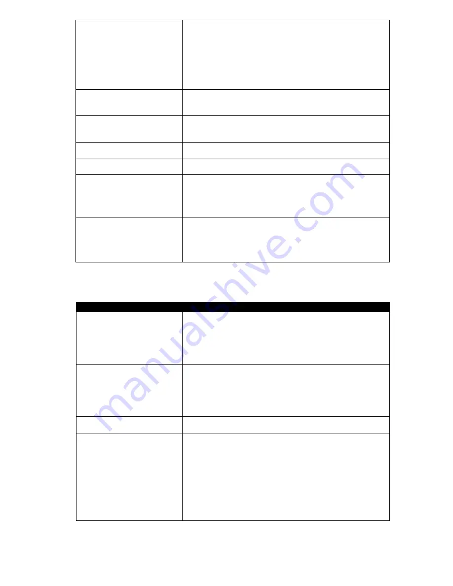
background image

36 


Return protection* 

 Group  of  parameters  available  after  connecting  return  sensor, 
responsible  for  protection  of  boiler  return  in  hydraulic  installation  with  4 
way  valve  equipped  in  mixer  servomotor,  point  9.1.  It  is  not  advised  to 
activate  functions  of  return  protection  because  it  may  cause  frequent 
stops  in  power  of  mixer  cycle.  Instead  this  it  is  recommended  to  use 
bigger  preset  temperatures  of  boiler  (70-75%)  what  in  combination  with 
installation  with  4  way  valve  (with  servomotor)  it  will  cause  automatic 
increase return temperature. 

Min. boiler  timep 

Minimum preset boiler temperatur

ę which can be set in user menu and 

minimum temp. which can be set automatically by controller, i.e. from 
night reductions etc.  

Max. biler time 

Maximum 

preset boiler temperaturę which can be set in user menu and 

minimum  temp.  which  can  be  set  automatically  by  controller,  i.e.  from 
night reductions etc. 

Reserve boiler  

Description in point 12.2 

Alarms 

Description in point 12.3  

Boiler cooling temperature 

Temperature  of  boiler  cooling  off. 

Above this temperaturę the controller 

activates  HW  pump  and  opens  mixer  cycles  to  allow  boiler  cooling  off. 
The controller activates HW pump if this temperature exceeds maximum 
value. The controller will not open mixer cycle when 

mixer setting

 = 

floor 

active


Pump off by therm.  

Options available 


NO (CH boiler pump is not activated when room thermostat starts 
operation), 


YES (CH boiler pump is deactivated when room thermostat starts 
operating) 


14.3


CH and HW SERVICE SETTINGS 


CH and HUW settings 


CH activation temperature 

Parameters  determines  the  tempera

turę  at  which  CH  boiler  pump  is 

activated.  It  protects  the  boiler  against  watering  due  to  cooling  off  with 
cold water returning from installation. Attention: Deactivating boiler pump 
only  does  not  guarantee  boiler  protection  against  watering  and 
consequently corrosion. Additional automatics should be used, i.e. 4 way 
valve or 3 way thermostatic valve. 

CH stand loading pause when HW l* 

Available  after  connecting  HW  sensor.  Prolonged  feeding  of  HW  silo 
during  priority  HW  deactivated  may  cause  to  overcooling  of  the  CH 
installation,  because  CH  pump  is  deactivated.  Parameter  CH  pump 
pause  during  feeding  HW  prevents  against  periodical  activating  CH 

pump  during  feeding  HW  silo.  CH  pump  after  this  time  will  activate  on 
constant, programmed time of 30s. 

Min. HUW temp. * 

Available  after  CH  sensor connecting.  It  is  a  parameter  by  which  it  can 
be reduced setting too low preset HW temperature. 

Max .HUW. temp. * 

Available  after  connecting  HW  sensor.  Parameter  determines  to  what 
maximum temperaturę HW silo will be heated during cooling the boiler in 
alarm  situations.  It  is  a  very  important  parameter,  because  setting  too 
high  value  of  it  may  cause  risk  of  scalding  with  HW.  Too  low  value  of 
parameter will cause that during boiler overheating it will not be possible 
to cool off the boiler to the HW silo. During design of HW installation, it is 
necessary  to  take  into  account  risk  of  damaging  the  controller.  Due  to 
breakdown  of  the  controller  water  in  the  silo  can  heat  up  to  dangerous 
temperature.  It  is  necessary  to  use  additional  protection  in  the  form  of 
thermostatic valves. 


Summary of Contents for ecoMAX850P1-A

Page 1: ...ions available in additional module B functions available in additional module MX 03 room panel ecoSTER200 non standard option USER MANUAL FOR MAINTENANCE AND INSTALLATION EDITION 1 0 APPLIES FOR HARDWARE MODULE A MODULE B PANEL v01 XX XX v 01 XX XX v 01 XX XX 2013 07 22 ...

Page 2: ......

Page 3: ...CTRIC CIRCUIT CONNECTION 24 12 5 SAFETY CONNECTIONS 26 12 6 ELECTRIC SCHEME 26 12 7 TEMPERATURE SENSORS CONNECTION 27 12 8 WEATHER SENSORS CONNECTION 27 12 9 WEATHER SENSORS CHECKING 27 12 10 OPTICAL SENSOR CONNECTION 28 12 11 MIXERS ROOM TEMPERATURE CONNECTION 28 12 12 BOILER ROOM THERMOSTAT CONNECTION 28 12 13 RESERVE BOILER CONNECTION 28 12 14 ALARMS SIGNAL CONNECTION 30 12 15 MIXER CONNECTION ...

Page 4: ...4 ...

Page 5: ... the feeder etc The controller is for boiler producers The boiler producer before its use should check if the cooperation between the controller and the boiler is correct and is not dangerous The controller is not a spark safe device It means that in emergency mode may be the source of a spark or high temperature which together with dust or flammable gases can cause fire or explosion The controlle...

Page 6: ...ser s manual of the controller is divided into two parts for the user and for the installer However in both parts vital information concerning safety is included That is why the user should get aquainted with both parts of the user s manual We do not take responsibility for damages caused by failing to observe the following user manual 4 DOCUMENTATION STORAGE We advise you to keep carefully this u...

Page 7: ...USER MANUAL OF THE CONTROLLER ecoMAX850P A ...

Page 8: ...nt hysteresis HUW disinfection Automatic disinfection SUMMER Activ temperature SUMMER Deactv temperature SUMMER Mixer settings 1 2 3 4 5 Preset mixer temperature Mixer room thermostat Weather control mixer Heating curve Mixer Curve shift Room temperaturę factor Night time decrease Boiler Mixer 1 Mixer 2 Mixer 3 Mixer 4 Mixer 5 HUW container Circulation pump General settings Clock Screen brightness...

Page 9: ...ted time spans C Boiler preset temperature during loading the hot water boiler HW M Boiler preset temperature increase from mixer circulation P weather control switch on for boiler circulation R active return protection B Preset temperature increase to load the buffer 5 Symbol signalling blowing operation 6 Symbol signalling fuel feeder operation 7 Symbol signalling central heating CH pump operati...

Page 10: ...ting parameters of its operation MENU button without connecting it to the electrical power After making sure that fuel is in the silo and the hatch is closed the boiler can be switched on 8 4 BOILER TEMPERATURE SETTING The preset boiler temperature and preset circuits temperature can be set in the menu Possible temperatures are restricted with range of respective service parameters of the controll...

Page 11: ...m which allows for gradual power reduction when approaching the preset temperature There are three power levels Maximal power 100 Medium power 50 Minimum power 30 Current power level is displayed on the screen as 3 segmented indicato rat the left side of boiler s icon Pic 7 Power level indicator in main window Each level can be allocated with seperate fuel feeding times and Air flush intensity whi...

Page 12: ...oiler settings Supervision Parameters of SUPERVISION mode are to be set in accordance to burner boiler producer s recommendations They should be so chosen to prevent the furnace from burning off during boiler s pauses the furnace should not at the same fire up to too high a temperature because it will cause too high a temperature of the boiler Operation and pause time of the feeder in SUPERVISION ...

Page 13: ...r is connected When the sensor is disconnected the information about it is displayed in the main window By selecting Menu HUW settings HUW Pump mode the user is able to Deactivate feeding the silo parameter Deactivated Setting HW priority by parameter Priority then CH pump is deactivated to feed the HW boiler quicker Set simultaneous operation of CH and HW pump with the parameter No priority Activ...

Page 14: ...his value is reduced correctly then room temperature increase will be stopped Mixer with weather sensor setting without room panel ecoSTER200 Set parameter mixer weather control in position on Adjust weather curve according to point 8 16 Using parameter paralel curve movement set required room temperature according to formula Required room temperature 20 C heating curve paralel movement Example To...

Page 15: ...utside temperature automatically controlled can be either preset boiler temperature and mixer cycles temperatures By correct adjustment of heating curve temperature of heating circuits is counted automatically depending on value of external temperature Thanks to that by choosing proper heating curve for given building room temperature remains approximately the same no matter what outside temperatu...

Page 16: ...ng comfort by reducing fuel consumption To activate time periods use parameter Night reduction for given cycle and activate it Night reductions can be defined separately in working days Saturdays and Sundays Pic 10 Window of time periods choosing It is needed to set the beginning and the end of given time period and value with which the preset temperature will be reduced Pic 11 Time periods editio...

Page 17: ...ip fuel level can also be seen in room panel ecoSTER200 room panel is not a standard option of the controller Pic 14 Auxiliary window with fuel level display Fuel level indicator service Each time when fuel silo is filled to required level it is necessary to press and keep the knob in main window Following info will appear Pic 15 Fuel level service After choosing and accepting YES fuel level will ...

Page 18: ...tings 8 22 INFORMATION Menu information enables view to measured temperatures and allows to check which of devices are currently activated Switching between following screens is done by twisting TOUCH and PLAY knob After connecting extension module of mixers information about auxiliary mixers are displayed Writing CAL in information window of mixer by position valve opening level stands for active...

Page 19: ...19 USER MANUAL OF CONTROLLER INSTALLATION AND SERVICE SETTINGS ecoMAX850P A ...

Page 20: ...ly it is necessary to isolate it thermically from surroundings and improve thermal contact with pipe Preset silo temperature must be set so high to ensure thermal power for mixer cycle when at the same time heating water returning to the silo RECOMMENDED SETTINGS Parameter Setting MENU Preset boiler temperature 75 80 C menu boiler settings Min preset boiler temperature 65 C menu service settings b...

Page 21: ... boiler settings Min preset boiler temperature 75 C menu service settings boiler settings CH pump activating temperature 55 C menu service settings CH and HUW settings Activating operation buffer service activated menu service settings buffer settings Buffer loading start temperature 50 menu service settings buffer settings Buffer loading stop temperature 75 menu service settings buffer settings M...

Page 22: ...ce active menu service settings buffer settings Buffer loading start temperature 50 menu service settings buffer settings Buffer loading stop temperature 75 menu service settings buffer settings Mixer service 1 2 3 4 active CH menu service settings mixer 1 4 settings Max Mixer preset temperature 1 2 3 4 70 menu service settings mixer 1 4 settings Mixer heating curve 1 2 3 4 0 8 1 4 menu mixer 1 4 ...

Page 23: ...nrays Temperature of storage and transport should be within scope 15 65 degrees C During transport the controller can not be exposed to vibrations bigger than typical for transport of boilers 12 CONTROLLER INSTALLATION 12 1 ENVIRONMENTAL CONDITIONS Due to fire risk it is forbidden to use the controller in proximity of explosive gases or dust Moreover the controller can not be used in conditions of...

Page 24: ...ntroller on assembly surface where 1 cover 2 base 3 screw for cover 4 plug 5 screw for assembly surface 6 assembly surface 12 4 ELECTRIC CIRCUIT CONNECTION The controller is adapted to current 230V 50Hz Features of installation 3 way with protecting wire made according with valid law Attention After deactivating the controller with the keypad there still can be a dangerous voltage on the connectio...

Page 25: ... is not acceptable to twist wires inside the device Wires inside the controller should be led through cable glands Cable glands should be screwed Make sure that glands are correctly screwed by pulling wire Length of isolation of external tire of wires should be minimal maximum 60mm If it is necessary to longer isolate the wire tire they should be connected with each other or other wires close to t...

Page 26: ...ure sensor CT2S T7 mixer temperature sensor TB connection of mixer room thermostat P controlling panel ecoSTER200 room panel with room thermostat function replacing TB or TM D D connection to additional modules B module B allows to service additional two mixer cycles and heating buffer cycle MX 03 additional module allows to service two additional mixers and circular pump A Lambda sond module L N ...

Page 27: ...es of the sensors are resistant to temperature not exceeding 100 degrees C 12 8 WEATHER SENSORS CONNECTION The controller cooperates solely with weather sensor type CT4 P The sensor should be installed on the coolest wall of the building Usually it is the northern wall under the roof The sensor shoul not be exposed to direct sunrays and rain The sensor should be installed at least 2 m above the gr...

Page 28: ...0 is shown on Pic 19 12 12 BOILER ROOM THERMOSTAT CONNECTION Room thermostat for boiler circuit can switch off the burner operation or switch off the CH boiler pump In order to thermostat switch off boiler operation select Thermostat selection for universal or ecoSTER T1 if room panel ecoSTER200 is connected Menu Service settings Boiler settings Thermostat selection For thermostat switch on the CH...

Page 29: ...ing alarms compatible with alarm signal codes causes activation of additional boiler When pellet boiler is fired up and its temperature exceedes preset value i e 25 degrees C then controller switches off additional boiler it will give constant power AC 6V for terminals 39 40 It will power the coil of transmitter and disconnecting its joints After decreasing boiler temperature below parameter tempe...

Page 30: ...roller 2 external alarm device 3 transmitter Then in order to operate correctly set proper code for active alarms signal in menu Menu Service settings Boiler settings Alarms Choosing value 127 causes activating electrical power between joints 39 40 connecting alarm extension in event of any of the alarms Setting this parameter for 0 will cause that the controller will not connect extension by any ...

Page 31: ...ectrical power to mixer servomotor with the controller according to point 12 4 and value servomotor producer s documentation Do not confuse opening direction with closing direction Connect electrical power to the controller and switch it into STAND BY mode Check if wires for mixer opening and closing are not swapped Go into MENU Manual control and open mixer by selecting Mixer 1 Opening ON By open...

Page 32: ... insulation which is thick enough to meet safety standards of the boiler 12 18 ROOM PANEL CONNECTION It is possible to equip the controller with room panel ecoSTER200 which has following functions Room thermostat controls up to 3 thermostats Controlling panel for the boiler Alarm signal Fuel level indicator 4 way connection Connect accordingly to point 12 6 2 way connection 2 wire connection requi...

Page 33: ...offe Cleaning airflow Supervision Supervision time Feed time Cycle time Blow in output Grate Flush time SUPERVISION Flush period SUPERVISION Min airflow output Fuel detection time Max burner temperature Additional feeder operation time Boiler settings Thermostat selection Return protection Min boiler temperature Max Boiler temperature Reserve boiler Alarms Boiler cooling temperature Pump off by th...

Page 34: ...king in bakery The burner operates with maximum power without modulation of power The burner deactivates with disconnecting thermostat joints 28 29 Boiler temperature sensor does not influence feeder operation Cycle time OPERATION Time of whole fuel feeding cycle in OPERATION mode OPERATION mode time feeding time OPERATION feeder pause time Airflow increase Value of the increase of the airflow pow...

Page 35: ...en by the user It is only used to limit the accessible scope of fan power It is not used in algorithm of controlling the fan It should be possibly small to allow the fan to rotate slowly without buzzing Fuel detection time Time is measured after decrease in brightness of flame below value flame detection After deducting this time the controller switches into firing up attempt After 3 failed attemp...

Page 36: ...CH and HW SERVICE SETTINGS CH and HUW settings CH activation temperature Parameters determines the temperaturę at which CH boiler pump is activated It protects the boiler against watering due to cooling off with cold water returning from installation Attention Deactivating boiler pump only does not guarantee boiler protection against watering and consequently corrosion Additional automatics should...

Page 37: ...etup YES It only refers to hydraulic installation with heat exchanger between open and closed circuit point 12 2 Available options YES boiler pump operates constantly in short circuit boiler exchanger it is not excluded i e from SUMMER function or HW priority NO pump operates normally 14 4 BUFFER SERVICE SETTINGS Buffer settings Activating operation Parameter serves to activating buffer operating ...

Page 38: ...this parameter Maximum mixer temperature Parameter serves two functions allows restricting setting too high mixer preset temperaturę Automatic control also will not cause exceeding preset temperature above value set in this parameter with parameter mixer setting activated FLOOR is also limit temperature of mixer sensor when mixer pump is deactivated For floor heating set the value below 45 degrees...

Page 39: ...39 15 DEFAULT SETTINGS RESTORING Default settings restore Restoring service settings settings from main menu are restored ...

Page 40: ...EDER MAX TEMP EXCEEDING Alarm appears after exceeding feeder temperaturę above service parameter MENU Service settings Burner settings Max burner temp If the feeder temperature increases above this value the controller will begin burning off procedure Alarm is deleted automatically after feeder temperature decrease by 10 C Function which protects against back fire does not work when feeder sensor ...

Page 41: ...atic furnace firing up In case of alarm all pumps are deactivated in order to not cause excessive cooling of the boiler Deleting is done by pressing TOUCH and PLAY button or by activating or deactivating the controller The cause of these alarms can be broken igniter or lack of fuel in the silo 16 7 FAILED ATTEMPT TO LOAD THE FEEDER This is so called silent alarm reminder It will take place by fail...

Page 42: ...n OFF then Lambda Sond readings will not have influence on controller s operation Amounts of air for given burner power are set in MENU Boiler settings Power modulation Boiler settings Output modulation 100 Blow in output 100 Feeder operation 100 Oxygene 50 H2 Hysteresis 50 Blow in output 50 Feeder operation 50 Oxygene 30 H1 Hysteresis 30 Blow in output 30 Feeder operation 30 Oxygene Boiler hyster...

Page 43: ...position it should be unlocked by untwisting the cover and twisting the button according to documentation of boiler producer Check the fan and replace it if necessary 5 Additional ffeder is not working module B Check if feeder wires are correctly connected to terminals Check if there is a jumper on terminals 1 2 of module B Check if feeder engine is not damaged In case when engine work can be hear...

Page 44: ... water Check if hydraulic installation is correctly made after closing the valve return temperature must increase above value of parameter Minimum return temperature The cause may be calibration of mixer valve wait until calibration is finished Active calibration is marked CAL in menu INFORMATION 20 COTROLLER CONFIGURATION BY BOILER PRODUCER The producer of boiler burner should adjust program para...

Page 45: ...45 ...

Page 46: ...46 ...

Page 47: ...47 ...

Page 48: ...48 Ignatki 27a 16 001 Kleosin Poland tel 48 85 749 70 00 fax 48 85 749 70 14 plum plum pl www pum pl www plumelectronics eu ...

Reviews: