background image

Installation manual SR85/CF COVER FEEDER

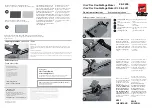
Figure 1, Top view

Route the Power Supply Harness, PSH, make sure
that the connector is on the infeed side of the
Booklet maker. Route it, between the inside of the
Top cover and the reinforcement by the right hinge.

Secure the PSH with
the cable holder.

Secure the PSH
with a cable tie.

Continue routing
the PSH in to the
hole in the frame.

6.

Continue routing the PSH in to the hole in the frame, according to figure 1.

NOTE: Make sure that you route the PSH so that you have approximately 13cm / 5” of the
shielded cable at the infeed side of the machine, according to figure 1.

7.

Secure the PSH with a cable holder, according to figure 1.

8.

Also secure the PSH with a cable tie, according to figure 1.

Step 5.

Step 7.

Step 8.

Step 6.

NOTE:

Approximately
13cm / 5” of the
shielded cable.

1-5

Summary of Contents for SR85 Cover Feeder

Page 1: ...October 2001 x17018 Installation Manual SR85 CF85 COVER FEEDER...

Page 2: ...all manual covers the installation of the SR85 Cover Feeder on to the Booklet maker SR 85 If you have any comments or remarks please contact us on one of the following numbers Email support oem plockm...

Page 3: ...ents 1 Installing the Cover Feeder 1 1 Unpacking 1 2 Cleaning the Fold rollers 1 3 Remove the Red cable ties 1 4 Routing the Power Supply Harness PSH 1 5 Attaching the Cover Feeder to the Top cover 1...

Page 4: ...mbly 4 Gas spring 5 Front Installation Bracket 6 Rear Installation Bracket 7 Power Supply Harness PSH Tie wraps Cable holders for the PSH 8 Communication cable 9 Cleaning plate and folder springs 4x 2...

Page 5: ...5 Remove the front and rear cover on the Booklet Maker according to REP 1 1 in the SR85 Service manual 6 Remove the two folder springs on the Front side according to figure 1 Step 6 7 Install two new...

Page 6: ...by holding in the Program select button and switching on the Main power switch according to figure 4 Figure 3 15 Close the Top cover 16 Let the Booklet Maker run for approximately 2 minutes 17 Turn of...

Page 7: ...ble from the Booklet maker 3 Remove the Infeed cover on the Booklet maker according to REP 1 4 in the SR85 Service manual 4 Open the Top cover 5 Route the Power Supply Harness PSH make sure that the c...

Page 8: ...H with a cable tie Continue routing the PSH in to the hole in the frame 6 Continue routing the PSH in to the hole in the frame according to figure 1 NOTE Make sure that you route the PSH so that you h...

Page 9: ...ith the Orange and Purple cable 13 Route the Red and Black cable to the right of the machine seen from the rear side 14 Connect the red cable to the Power connector according to figure 2 15 Connect th...

Page 10: ...ansformer 20 Loosen screw no 9 on the terminal block and leave the White wire according to figure 3 21 Insert the Orange wire from the PSH and the existing White wire to no 9 on the terminal block Fas...

Page 11: ...from the PSH and the existing Blue wire to no 10 on the terminal block Fasten the screw according to figure 3 24 Reinstall the Infeed cover according to REP 1 4 in the SR85 Service Manual 25 Reinstall...

Page 12: ...stallation kit to the black bracket in the machine according to Figure 1 Figure 2 Top view 3 Remove the Front cover on the Cover Feeder by removing a 7mm screw NOTE The DFD calibration strip is locate...

Page 13: ...ide of the Top cover Slide the Bracket upwards so the fold catches the edge of the Top cover according to figure 3 NOTE Make sure you routed the PSH correctly so it will not interfere when you are clo...

Page 14: ...install the Front Installation Bracket in the Cutout on the Cover Feeder frame according to figure 4 Figure 4 view of lifting the Cover Feeder and installing the Front Installation Bracket Figure 5 vi...

Page 15: ...ccording to figure6 Figure 7 Infeed view 16 Adjust the Cover Feeder so that there is an equal gap between the Jam clearance baffle and the two brackets on the infeeder assembly Figure 7 Push the Cover...

Page 16: ...he Top cover according to figure 8 Paper Bin spring Paper Bin spring Feed roller assembly 19 Connect the PSH and the ground wire to the rear of the Cover Feeder Secure the PSH with a cable holder on t...

Page 17: ...the Copier Finisher to the Cover feeder according to figure 10 25 Connect the Communication cable that was included in the Installation kit between the Cover Feeder and the Booklet maker according to...

Page 18: ...the adjustable side guide up against the sheets until there is no clearance 7 Move the adjustable Air nozzle so that the green stripe on the Air nozzle bracket is up against the paper stock 8 Set the...

Reviews: