12
ENGLISH
L289N
1b
1
1a
0
1
Battery Pack
GND
VMS
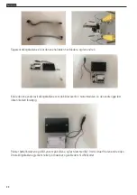
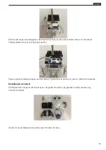
The following diagram shows how to connect the power switch to the battery pack and the L298N
board. Caution: Do not have the UNO Board connected to your computer at the same time as the L298N
motor board as the module can drain a large amount of power from the USB port and burn it out. Always
disconnect the battery pack from the device before connecting it via USB.
Wire connection
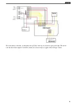
The final step is to connect all the modules together via the wires. The following diagram shows the
connection map. Take it slow and easy, you can also see the second connection table.
UNO board Sensor
Shield
L289N
Battery
Box
Motor
left
Motor
Right
Servo Ultrasonic
sensor
GND
GND
VMS
VMS
+(Left)
+(red)
-(Left)
-(black)
+(Right)
+(red)
-(Right)
-(black)
V E
NA
6
IN1
9
IN2
10 I
N3
11 I
N4
V
ENB
G
GND
V
5V+
5
S
V
+
G
-
V
+
A1
Trig
A0
Echo
G
-


