background image

TABLE OF CONTENTS

SCOPE 

9

RELATED PUBLICATIONS 

9

NOTICES 

9

GENERAL DESCRIPTION 

11

DRIVE CHARACTERISTICS 

13

RACK MOUNT AND DESKTOP CONFIGURATIONS 

13

TOWER CONFIGURATION 

15

FILENET LIBRARY CONFIGURATION 

17

PLASMON 1800 LIBRARY CONFIGURATION 

19

DIMENSIONS AND WEIGHTS 

21

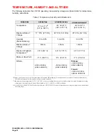
TEMPERATURE, HUMIDITY AND ALTITUDE 

22

MEDIA ENVIRONMENTAL CHARACTERISTICS 

23

SHOCK AND VIBRATION 

23

AC POWER REQUIREMENTS 

24

AC GROUND 

24

AC POWER CORD 

24

POWER SUPPLY OUT-OF-RANGE PROTECTION FEATURES 

24

HEAT DISSIPATION 

24

TILT RANGE 

24

PARTICULATE LIMITS 

25

WARNING LABELS 

25

UNPACKING AND REPACKING INSTRUCTIONS 

27

UNPACKING THE LD 8100 

27

DESKTOP, RACK MOUNT AND LIBRARY CONFIGURATIONS 

27

TOWER CONFIGURATION 

29

INSPECTING THE LD 8100 

31

REPACKING THE LD 8100 

31

DESKTOP, RACK MOUNT AND LIBRARY CONFIGURATIONS 

32

TOWER CONFIGURATION 

34

INSTALLATION AND DE-INSTALLATION 

35

INSTALLATION REQUIREMENTS 

35

QUICK RELEASE RACK MOUNT KIT INSTALLATION 

36

QUICK RELEASE RACK MOUNT DE-INSTALLATION 

47

SCSI BUS CONSIDERATIONS 

48

CONNECTING POWER AND SCSI CABLES 

50

CONNECTING THE POWER CORD 

50

CONNECTING MULTIPLE DEVICES 

50

CONNECTING A SINGLE DEVICE 

51

CONNECTOR VERIFICATION 

52

Summary of Contents for LD 8100

Page 1: ...THE PLASMON 8000 SERIES LD 8100 OPTICAL DISK DRIVE P N 9662915 B USER MANUAL ...

Page 2: ...his manual is prohibited without the express permission of Plasmon Laser Magnetic Storage LMS Plasmon LMS reserves the right to make changes in this document and the product referred to herein without prior notice 2000 Plasmon Laser Magnetic Storage ...

Page 3: ... unit is installed When the unit is mounted in an equipment rack or cabinet be certain that the internal temperature within the rack or cabinet does not exceed the limits defined in the Product Specification or this document To ensure the integrity of safety features of this unit maintenance must be performed only by qualified service personnel using designated Plasmon LMS parts In case of fire or...

Page 4: ...egestell oder einen Geräteschrank eingebaut ist darauf zu achten daß die interne Temperatur im Gestell oder Schrank nicht über die in den Produktspezifikationen oder diesem Dokument angegebenen Grenzwerte hinausgeht Um ein ordnungsgemäßes Funktionieren der Sicherheitsmerkmale dieses Gerätes zu gewährleisten dürfen Wartungsarbeiten nur von qualifiziertem Fachpersonal ausgeführt werden Es sind darüb...

Page 5: ...ry the user should consult the dealer or an experienced radio television technician for additional suggestions A pamphlet by the FCC How to Identify and Resolve Radio TV Interference Problems is available from the US Government Printing Office Washington D C 20402 Stock No 044 000 00345 4 CDRH COMPLIANCE LD 8100 contains a Class 1 Laser Product This product complies with 21CFR Chapter 1 Subchapter...

Page 6: ......

Page 7: ...24 HEAT DISSIPATION 24 TILT RANGE 24 PARTICULATE LIMITS 25 WARNING LABELS 25 UNPACKING AND REPACKING INSTRUCTIONS 27 UNPACKING THE LD 8100 27 DESKTOP RACK MOUNT AND LIBRARY CONFIGURATIONS 27 TOWER CONFIGURATION 29 INSPECTING THE LD 8100 31 REPACKING THE LD 8100 31 DESKTOP RACK MOUNT AND LIBRARY CONFIGURATIONS 32 TOWER CONFIGURATION 34 INSTALLATION AND DE INSTALLATION 35 INSTALLATION REQUIREMENTS 3...

Page 8: ...9 SETTING THE CDE CURS OPTION 70 SETTING THE BUSY OPTION 70 SETTING THE MODSEL RA OPTION 71 SETTING THE MM SPINUP OPTION 71 SELECT TARGET NEGOTIATION 72 VIEWING DIAGNOSTIC RESULTS OR PERFORMING DIAGNOSTICOPERATIONS DIAGNOSTICS 73 SET THE INTERNAL DRIVE SERIAL NUMBER SET SERIAL 78 TEST MODE 80 MEDIA CARTRIDGE HANDLING 81 SETTING THE WRITE PROTECTION SWITCH 83 AFFIXING LABELS TO THE MEDIA CARTRIDGE ...

Page 9: ... conditions that could potentially result in personal injury fire hazard or equipment damage CAUTION A CAUTION is used to warn of undesirable procedures or of situations in which equipment damage could potentially result NOTE A NOTE is used to emphasize an area of text or to provide additional information PUBLICATION PART NUMBER LD 8100 LF 8120 LF 8600 LF 8602 Product Specification 97663035 LD 810...

Page 10: ...proper use or maintenance Repairs or replacements not covered by the warranty will be invoiced at Plasmon then current prices The warranty is void when installation service or repairs are performed by un certified personnel when the product is affected by unauthorized alterations modifications or other tampering or misuse when the product is incorporated into a system which causes or involves any ...

Page 11: ...6000 and LM 4000 media Contact Plasmon LMS for availability and ordering information for the LM 4000 media option The LD 8100 is available in a Rack Mount Desktop Tower FileNet Library and Plasmon Library configurations offering support for varied operating orientations and installation environments see figure below Figure 1 LD 8100 Configurations FILENET LIBRARY CONFIGURATION TOWER CONFIGURATION ...

Page 12: ...anel of the Rack Mount the Desk Top and the Tower configurations The ADP may be located on the rear panel of the Plasmon Library and the Filenet configurations The ADP may also be used as a standard serial port for setting the SCSI ID The LD 8100 drive implements the Small Computer System Interface SCSI via standard SCSI 2 micro connectors 68 pin located on the rear panel Single ended and differen...

Page 13: ...nt configuration is designed for horizontal operation and slide mounting in an EIA standard 19 in rack The Rack Mount configuration is installed in a rack using the Quick Release Rack Mount Kit refer to the Installation section of this manual Figure 2 LD 8100 Rack Mount Drive The LD 8100 Desktop configuration is designed for horizontal operation as a stand alone device on a table top The Desktop c...

Page 14: ...cludes a DOC ADP Blank Panel MCLI Blank Panel AC Power Switch Receptacle SCSI 2 I O Panel Assembly and a ground connector The figure below illustrates the rear panel layout A Fan Grill and filter element are installed over the fan vent to filter out contaminants from cooling air entering through the rear panel Figure 5 LD 8100 Rack Mount Rear Panel BEZEL MEDIA CARTRIDGE LOADING DOORS DOC ADP DOC A...

Page 15: ...device on an open floor or beside a desk The Tower configuration includes an enclosure for both the LD 8100 and the pedestal The pedestal is supported by four casters which can be locked to prevent unintentional movement Figure 6 LD 8100 Tower Configuration 67 3 cm 26 5 in 18 9 cm 7 4 in 30 5 cm 12 0 in 48 6cm 19 1 in 66 7cm 26 2 in ...

Page 16: ...rear panel of the LD 8100 Tower configuration and identifies the location of the AC power switch Receptacle ground connector SCSI 2 I O Panel Assembly DOC ADP Blank Panel and MCLI Blank Panel A Fan Grill and filter element are installed over the fan vent to filter contaminants from cooling air entering through the rear panel Figure 8 Rear View of LD 8100 Tower DOC ADP MEDIA CARTRIDGE LOADING DOOR ...

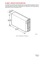
Page 17: ...d is designed for vertical or horizontal mounting and for operation in a FileNet Library The FileNet Library configuration has the same major assemblies as the other LD 8100 configurations but is configured for use in a FileNet Library by adding the MCLI connector and Registration Panel Figure 9 FileNet Library Configuration ...

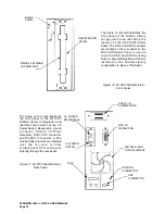
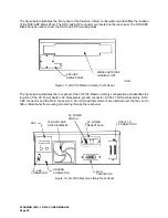
Page 18: ...Library Front Panel The figure on the right illustrates the rear panel of the LD 8100 FileNet Library configuration and identifies the location of the AC Power Switch Receptacle ground connector SCSI 2 I O Panel Assembly DOC ADP connector and the MCLI connector A Fan Grill and filter element are installed over the fan vent to filter contaminants from cooling air entering through the rear panel Fig...

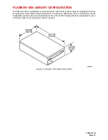
Page 19: ...ezel or Registration Panel is designed for horizontal mounting and operation in a Plasmon 1800 Series Library The Plasmon Library configuration has the same major assemblies as the other LD 8100 configurations but is adapted for use in a Plasmon 1800 Library by adding an MCLI connector Figure 12 Plasmon 1800 Series Library Drive ...

Page 20: ...tes the rear panel of the LD 8100 Plasmon Library configuration and identifies the location of the AC Power Switch AC Receptacle ground connector SCSI 2 I O Panel Assembly DOC ADP connector and the MCLI connector A Fan Grill and filter element are installed over the fan vent to filter contaminants from cooling air entering through the rear panel Figure 14 LD 8100 Plasmon Library Rear Panel DOC ADP...

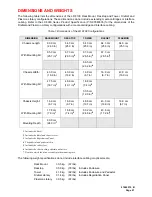
Page 21: ...e following weight specifications do not include interface cabling or optical media DIMENSION RACKMOUNT DESKTOP TOWER FILENET PLASMON Chassis Length With Mounting Kit 60 9 cm 24 0 in 64 3 cm 25 3 in 64 3 cm 25 3 in 64 3 cm 25 3 in 64 3 cm 25 3 in 65 3 cm 25 7 in 1 67 3 cm 26 5 in 2 67 3 cm 26 5 in 2 67 3 cm 26 5 in 3 66 5 cm 26 2 in 4 Chassis Width With Mounting Kit 43 0 cm 16 9 in 43 0 cm 16 9 in...

Page 22: ...ture is derated linearly above 300 m altitude to 38 C 100 4 F at 2 000 m altitude 3 See the LD 8100 LF 8600 LF 8602 Product Specification P N 97663035 for more information concerning the temperature and humidity operating range CONDITION OPERATING NONOPERATING STORAGE TRANSIT1 Temperature 10 to 42 C 2 50 to 108 F 40 to 66 C 40 to 151 F 40 to 66 C 40 to 151 F Maximum Rate of Change 11 C hr 20 F hr ...

Page 23: ...0 F to 131 o F 10 C to 30 C 50 F to 86 0 F Relative Humidity no condensation 5 80 5 90 5 80 Wet Bulb Temperature 26 C max 78 8 F 26 C max 78 8 F 26 C max 78 8 F Temperature Gradient 10 C hr max 18 0 F hr max 31 C hr max 55 8 F hr max 5 C hr max 9 0 F hr max Air Pressure N A N A N A Solar Radiation N A Case to be kept closed Not to be stored in direct sunlight CONDITION OPERATING NONOPERATING1 STOR...

Page 24: ...nnector is a 6 mm 0 24 in M4 stud with a nut and lock washer AC POWER CORD The type of AC power cord that is supplied with the LD 8100 is based on the configuration ordered and the destination country POWER SUPPLY OUT OF RANGE PROTECTION FEATURES The LD 8100 power supply provides over and under voltage protection over current protection and over temperature protection Should an out of range condit...

Page 25: ...nd media causing degradation in drive performance Refer to the Operator Maintenance section for media cleaning and air filter cleaning instructions WARNING LABELS The LD 8100 is classified as a laser product As such it is subject to United States Federal requirements covering laser products The warning labels shown in the figure below are necessary to ensure compliance with Federal regulations and...

Page 26: ...PLASMON LMS LD 8100 USER MANUAL Page 26 ...

Page 27: ...the LD 8100 A wheeled cart is recommended for transporting the LD 8100 within a building Precautions should be taken to guard against sudden bumps and jarring DESKTOP RACK MOUNT AND LIBRARY CONFIGURATIONS To unpack the LD 8100 Desktop Rack Mount and Library configurations refer to the next figure and perform the following procedure 1 Cut the bands that secure the outer carton to the lower carton 2...

Page 28: ...gure 16 Unpacking the LD 8100 Desktop Rack Mount and Library Configurations OUTER CARTON FOAM CUSHION ESD PACKING MATERIAL LD 8100 FOAM PADS LOWER CARTON MOUNTING SLIDE RACK MOUNT CONFIGURATION FRONT FOAM CUSHION OPTION ACCESORY TRAY KIT PALLET ...

Page 29: ...e LD 8100 must be unpacked repacked and transported by two persons Physical injury can result if one person attempts to transport or lift the LD 8100 A wheeled cart is recommended for transporting the LD 8100 within a building Precautions should be taken to guard against sudden bumps and jarring Ensure that all four casters are locked Lift the front end of the LD 8100 high enough to remove the bot...

Page 30: ...NUAL Page 30 Figure 17 Unpacking and Repacking the LD 8100 Tower Configuration REAR FOAM CUSHION FRONT FOAM CUSHION OPTIONS ACCESSORIES TRAY CARTON ESD PACKING MATERIAL LD 8100 BOTTOM CUSHION FOAM BUMPER HINGED WOODEN RAMP PALLET ...

Page 31: ...te by exposing the LD 8100 to the operating environment for at least 6 hrs before powering on the unit REPACKING THE LD 8100 The LD 8100 should be repacked using the original packing material Perform the following procedures to repack the LD 8100 for shipment CAUTION To prevent lifter mechanism damage the BASEPLATES must be in the parked position before preparing the unit for shipment The baseplat...

Page 32: ... the chassis c Turn the Manual Release Knobs located at the front of the drive in a counterclockwise direction until free rotation is restricted Figure 18 Closing the Upper and Lower Baseplates Before Shipment d Reinstall the Bezel Assembly onto the front panel by positioning the Bezel Assembly near the front of the drive with the bottom of the Bezel angled in closer to the drive This ensures that...

Page 33: ...a building Precautions should be taken to guard against sudden bumps and jarring 4 Place the LD 8100 into the lower carton 5 Place the ESD packing material on top of the drive 6 Position the foam cushions around the drive 7 Place the power and interface cables User Manual and other accessories into the options and accessories tray and place this tray on the foam cushions 8 If packing an LD 8100 Ra...

Page 34: ...ront panel WARNING The LD 8100 must be repacked and transported by two persons Physical injury can result if one person attempts to transport or lift the LD 8100 A wheeled cart is recommended for transporting the LD 8100 within a building Precautions should be taken to guard against sudden bumps and jarring 3 Unlock the casters and carefully roll the drive to its packing site 4 Remove all packing ...

Page 35: ...on system that has a direct connection to earth ground Terminated Terra TT network ground connected This unit is not suitable for use on a floating ground Interrupted Terra IT network Ensure the drive is connected to a power distribution system with an adequate current handling capacity The following table lists the clearances required for air circulation cartridge insertion removal maintenance an...

Page 36: ...radiation can be emitted if the unit is opened QUICK RELEASE RACK MOUNT KIT INSTALLATION This procedure provides the instructions for installing an LD 8100 into a standard EIA 19 in rack Before the LD 8100 is installed ensure that the site installation requirements are met refer to the Installation Requirements section in this manual The Desktop Tower FileNet Library and Plasmon Library configurat...

Page 37: ...eight No 10 flat washers Refer to the next figure for an illustration of the Quick Release Kit s major parts Figure 20 Contents of Rack Mount Quick Release Kit NUT PLATE 4 PLACES MOUNTING BRACKET 4 PLACES RIGHT SLIDE ASSEMBLY LEFT SIDE ASSEMBLY OUTER SLIDE MEMBER INTERMEDIATE SLIDE MEMBER ACCESS SLOT INNER SLIDE MEMBER SLIDE RELEASE LATCHES QUICK DISCONNECT ...

Page 38: ...ermediate Slide Channels by the Slide Release Latch and the Inner Slide Release Button The Slide Release Latch is located at the front of the Inner Slide Channel and the Inner Slide Button is located on the inside of the Inner Slide Channel Figure 21 Separating the Inner Slide Channel from the Intermediate Slide Channel 1 Lift up the Slide Release Latch at the front of the Inner Slide Channels and...

Page 39: ...e Front Mounting Brackets are properly positioned before the mounting screws are tightened After they are properly positioned the Front Mounting Brackets have to be securely fastened to the Outer Slide Channel to prevent them from moving The same is not true for the Rear Mounting Brackets their mounting hardware must be loosely installed so that the position of the Rear Mounting Brackets can be ad...

Page 40: ...orward end of the Outer Slide Channel The mounting holes and access slots can be aligned by pulling the Intermediate Slide Channel in or out of the Outer Slide Channel until the access slots and mounting holes line up After this alignment is made the mounting screws can be inserted through the Intermediate Slide Channel access slots through the Outer Slide Channel mounting holes and into the Front...

Page 41: ...s moving the front mounting bracket toward the front of the Outer Slide Channel until it stops The detail view of the front mounting bracket see next figure depicts a front mounting bracket that has been properly installed 7 Move the front mounting brackets toward the front of the Outer Slide Channels until they stop and the mounting screws are at the rear end of the mounting slots Tighten securel...

Page 42: ...justment 11 Hold the slide assembly in position on the cabinet rails with the front bracket held firmly against its rail Slide the rear bracket until it also is flush with the rear rail Remove the slide assembly and securely tighten the rear bracket in that position 12 Replace the slide assemblies in their cabinet positions and secure with the preselected hardware Each bracket should receive two s...

Page 43: ...LOOSELY FOR ADJUSTING FRONT MOUNTING BRACKET SLIDE ASSEMBLY MOUNTING SCREW 4 PLACES FLAT WASHER 4 PLACES MOUNTING BRACKET RACK RAIL CABINET RAIL WITH CLEARANCE HOLES NUT PLATE SEE FIGURE ON PAGE 34 FRONT BRACKET 10 32 SCREW FLAT WASHER SEE DETAIL DRAWING FOR NUT PLATE CONFIGURATION SCREWS INSTALLED AND TIGHTENED ...

Page 44: ...Any attempt to lift the LD 8100 without assistance may result in personal injury 14 Carefully lift the LD 8100 and mate the left and right Inner Slide Channels with the left and right Intermediate Slide Channels 15 Push the LD 8100 chassis and Inner Slide Channels toward the rack until a slide stop is encountered INTERMEDIATE SLIDE CHANNEL BEZEL BRACKET BEZEL BEZEL BRACKET INNER SLIDE CHANNEL INTE...

Page 45: ... re install the Bezel Assembly on the drive position the Bezel Assembly near the front of the drive with the bottom of the bezel angled in closer to the drive This ensures that the bottom Velcro fasteners of the Bezel Assembly are aligned with the bottom Velcro fasteners of the drive Figure 27 Re installing Bezel Assembly Rack Mount Installation 19 Begin sliding the Bezel Assembly onto the drive l...

Page 46: ...te and the unit is ready for cable installation Refer to the SCSI Bus Considerations and Connecting Power and SCSI Cables sections for cabling instructions Figure 28 Contents of Rack Mount Quick Disconnect Kit NUT PLATE 4 PLACES MOUNTING BRACKET 4 PLACES RIGHT SLIDE ASSEMBLY LEFT SLIDE ASSEMBLY OUTER SLIDE MEMBER INTERMEDIATE SLIDE MEMBER QUICK DISCONNECT ACCESS SLOT INNER SLIDE MEMBER SLIDE RELEA...

Page 47: ...t in personal injury 2 Lift both Slide Release Latches up and then pull the drive away from the rack to the fully extended position 3 Verify that the rack is stable 4 Press and hold both Inner Slide Channel Release Buttons while pulling the drive out of the Intermediate Slide Channels One person can press the Inner Slide Channel Release Buttons and the second person can slide the drive from the In...

Page 48: ...ed The SCSI interface cabling used to interconnect an LD 8100 to a host can be daisy chained between SCSI devices as illustrated below One interface cable is required between each pair of SCSI devices Figure 29 Host to LD 8100 Daisy Chain Cable Connections A terminator must be installed on the vacant connector of the last SCSI device in SCSI bus chain NOTE You must first determine the type of term...

Page 49: ...ection Normally the termination function is built into the host adapter Power for the external terminator is supplied by the LD 8100 and may also be supplied from another device in the SCSI daisy chain Refer to the Accessories section of this manual for a list of SCSI bus terminators cables and their Plasmon LMS part numbers HOST HOST SCSI CONNECTOR LD 8100 SCSI CONNECTORS TERMINATOR TERMINATOR ...

Page 50: ...nstallation location 2 Ensure facility power is available and the AC power cord connector male end will match the site AC power wall outlet 3 Ensure that the AC power switch on the LD 8100 rear panel is set to the OFF O position 4 Plug the AC power cord connector female end into the AC power receptacle on the LD 8100 rear panel 5 Plug the AC power cord connector male end into a wall outlet Figure ...

Page 51: ...rdance with the LD 8100 LF 8120 LF 8600 LF 8602 SCSI Interface Specification P N 97662164 Figure 32 Multiple LD 8100 SCSI Interface Cable Connections CONNECTING A SINGLE DEVICE To install a SCSI interface cable for a single device configuration 1 Plug one end of the SCSI interface cable into the vacant SCSI interface connector on the host 2 Plug the other end of the interface cable into a SCSI I O...

Page 52: ...nections CONNECTOR VERIFICATION Prior to powering on the system 1 Verify proper termination at the host adapter if applicable 2 Verify proper termination at the last LD 8100 on the bus if applicable Refer to the Operating Instruction section in this manual for power on procedures TERMINATOR ...

Page 53: ...t status messages LOAD MENU Switch In operating mode the LOAD MENU switch controls the loading and unloading of media cartridges In Configuration mode the LOAD MENU switch steps through the menu of configurable parameters TEST SELECT Switch In operating mode the TEST SELECT switch invokes the diagnostic self test In Configuration mode the TEST SELECT switch scrolls through the options available fo...

Page 54: ...urning the power on again Figure 35 AC Power Switch Positions Perform the following procedure to power on the LD 8100 1 Ensure that the LD 8100 is properly connected see the Connecting Power and SCSI Cables and the Connector Verification sections in this manual 2 Set the AC Power Switch to the ON I position and verify that air is flowing through the LD 8100 3 Verify that the WRITE PROTECT indicato...

Page 55: ...rite data Configuration mode allows an operator to view and set drive parameters Test mode invokes drive diagnostics to verify proper drive operation OPERATING MODE The LD 8100 enters the Operating mode after being powered on and displays the Insert Disk message on the DOC The Insert Disk message indicates the LD 8100 is ready to accept a media cartridge Whenever the DOC displays the Insert Disk m...

Page 56: ...isplayed when the media cartridge is available for use by the host When the DOC is displaying the Ready message a media cartridge can be unloaded and removed from the drive by pressing the LOAD MENU switch The media may also be unloaded by command from the host The media will be unloaded and the cartridge can be removed by pulling the cartridge straight out from the front of the drive as illustrat...

Page 57: ...AN Insert Cartridge Insert Disk Insèrer Disq Einfügen Loading Media Loading Charger Ladend Drive Ready Ready Prêt Bereit Drive Locked Locked Verrouillé Gesperrt Drive Reading Reading Lecture Lesend Drive Writing Writing Eriture Schreibend Unloading Cartridge Unloading Déchargement Entladend Remove Cartridge Remove Disk Retirer Disq Entfernen Drive is in Reset SCSI Reset SCSI Reinit SCSI Reinit Ill...

Page 58: ...le parity checking Parity Set language option to English French or German Language Enable or disable write protect option Wrt Prot Enable or disable media AutoSpin option AutoSpin Enable or disable load switch option Load SW Enable or disable read ahead Rd Ahead Enable or disable Controller Detected Error blink option CDE Curs Enable or disable Busy option Busy Enable or disable Mode Select Read A...

Page 59: ... a media cartridge is loaded on the drive spindle View Config Set Config Diagnostics Set Serial This is the entry point into the Configuration menu Press the SELECT switch to enter a submenu allowing the user to view the drive operating parameters firmware revisions and hardware serial numbers Press the MENU switch to select the next option in the Main menu Press the SELECT switch to enter a subme...

Page 60: ...TH SWITCHES SIMULTANEOUSLY FROM ANY MENU TO RETURN TO THE MAIN MENU SELECT MENU View Config SELECT MENU Set Config MENU Diagnostics SELECT MENU Set Serial SELECT ENTER SERIAL NUMBER ENTRY MENU ENTER DIAGNOSTIC MENU ENTER SET CONFIG MENU ENTER VIEW CONFIG MENU MAIN MENU ...

Page 61: ...ress the MENU switch to select the next option in the View Configuration menu View HW S Ns Press the SELECT switch to display the serial numbers These include serial numbers for the Drv SN Woodi Rws A Rws B Oma A Oma B and Dpc Press the MENU switch to select the next option in the View Configuration menu View HW P Ns Press the SELECT switch to display the hardware part numbers These include part n...

Page 62: ...ches simultaneously The display will show the message which appeared prior to the drive entering the Configuration mode Figure 39 View Config Menu SELECT MENU View Current MENU View FW Revs SELECT MENU View HW S Ns SELECT MENU View HW P Ns SELECT DISPLAY CURRENT SELECTIONS DISPLAY FW REVISIONS DISPLAY HW SERIAL NUMBERS DISPLAY HW PART NUMBERS PRESS BOTH SWITCHES SIMULTANEOUSLY FROM ANY MENU TO RET...

Page 63: ... Press the SELECT switch to turn AutoSpin on or off When the desired state on or off is displayed press the MENU switch to enter that state for AutoSpin and select the next option in the Set Configuration menu Load SW Press the SELECT switch to enable or disable the LOAD switch on the DOC When the desired state on or off is displayed press the MENU switch to enter that state for load switch and se...

Page 64: ... will show the message which appeared prior to the drive entering the Configuration mode Figure 40 Set Config Menu Part 1 SELECT MENU SET DEFAULT SET VALUES TO DEFAULT SELECT MENU SCSI ID 0 0 7 MENU PARITY ON ON OFF SELECT MENU LANGUAGE ENG SELECT FRH GRM MENU WrtProt OFF ON OFF SELECT MENU AutoSpin ON ON OFF SELECT ENG MENU Load SW ON ON OFF SELECT A FROM LAST MENU SELECTION PRESS BOTH SWITCHES S...

Page 65: ... SELECT MENU SELECT MENU ON OFF ON OFF ON OFF PRESS BOTH SWITCHES SIMULTANEOUSLY FROM ANY MENU TO RETURN TO SET CONFIG SET CONFIG MENU PRESS BOTH SWITCHES SIMULTANEOUSLY FROM SET CONFIG TO RETURN TO THE MAIN MENU MAIN MENU Negotiation SELECT TargSDTR MENU MENU SELECT MENU SELECT TargWDTR SELECT SELECT MM SpinUp OFF OFF ON OFF ON MENU SELECT PRESS BOTH SWITCHES SIMULTANEOUSLY ...

Page 66: ...wever each device connected to the same SCSI bus must have a unique SCSI ID Perform the following procedure to set the LD 8100 s SCSI ID number 1 Enter the Configuration mode by pressing both the LOAD MENU and TEST SELECT switches simultaneously 2 Press the MENU switch until Set Config is displayed 3 Press the SELECT switch to enter the Set Configuration menu 4 Press the MENU switch until SCSI ID ...

Page 67: ... SELECT switches again to exit Configuration mode SETTING THE LANGUAGE The language option enables the user to select the language used by the LD 8100 to display messages in the Operating mode English is the only available language for Configuration mode Perform the following procedure to set the operating mode display language 1 Enter the Configuration mode by pressing both the LOAD MENU and TEST...

Page 68: ...ING THE MEDIA AUTOSPIN OPTION The media AutoSpin load option enables a user to choose between automatically or manually spinning up and initializing a media cartridge after it has been inserted into the drive If the AutoSpin option is enabled each media cartridge inserted into the drive will be automatically spun up and initialized If the AutoSpin option is disabled the LOAD MENU switch will have ...

Page 69: ...enu Simultaneously press the LOAD MENU and TEST SELECT switches again to exit Configuration mode SETTING THE READ AHEAD OPTION The read ahead option often improves the overall read data transfer rate of the LD 8100 in applications which require continuous blocks of data to be read as compared to the same subsystem without read ahead Perform the following procedure to turn read ahead on or off 1 En...

Page 70: ... Press the SELECT switch to scroll through the states for CDE Curs off on When the desired state is displayed press MENU to enter the state and move to the next option in the Set Configuration menu 6 Simultaneously press the LOAD MENU and TEST SELECT switches to move up to the main menu Simultaneously press the LOAD MENU and TEST SELECT switches again to exit Configuration mode SETTING THE BUSY OP...

Page 71: ...eously press the LOAD MENU and TEST SELECT switches again to exit Configuration mode SETTING THE MM SPINUP OPTION When enabled the Media Management Spin Up MM SpinUp option allows the LaserDrive to read necessary media management information during spin up If not enabled the media management information will be recovered on the first media access command Perform the following procedure to enable o...

Page 72: ...usly 2 Press the MENU switch until Set Config is displayed 3 Press the SELECT switch to enter the Set Configuration menu 4 Press the MENU switch until Negotiation is displayed 5 Press SELECT switch TargSDTR is displayed Press SELECT to toggle between OFF or ON 6 When the desired selection has been made press MENU to display TargWDTR 7 Press SELECT to toggle between OFF and ON 8 Simultaneously pres...

Page 73: ...ill be cleared To Continue Press Select will appear Press the MENU switch if you do not want to clear the nonvolatile memory NvRAM initialization variables press the SELECT switch to clear the NvRAM initialization variables in the drive Press the MENU switch to select the next option in the Diagnostics menu View CDEs Press the SELECT switch to view the controller detected error CDE The DOC will di...

Page 74: ...tch to select the number of times the test s is to be performed Use the MENU switch cycle through all four digits Press the MENU switch to select the next option in the Diagnostics Menu View RTPM Press the SELECT switch to view the RTPM Real Time Performance Monitor status If no RTPM error has occurred the DOC will display No RTPM Err If an RTPM error has occurred the DOC will display the media se...

Page 75: ...e SELECT switch if an RTPM error has not occurred the message No RTPM Err will briefly appear and the display will return to Clear RTPM If an RTPM has occurred a confirmation message will be displayed Press the SELECT switch to clear the RTPM error and enable writing Press the MENU switch to select the next option in the Diagnostic Park Drive menu without clearing the RTPM error The drive will not...

Page 76: ...ar SELECT Display Default Information Enter Sensor Display Mode Test End 0 Test Cycles SELECT SELECT MENU A MENU 0 9 0 9 FROM LAST MENU SELECTION MAIN MENU PRESS BOTH SWITCHES SIMULTANEOUSLY FROM SET CONFIG TO RETURN TO THE MAIN MENU PRESS BOTH SWITCHES SIMULTANEOUSLY FROM ANY MENU TO RETURN TO SET CONFIG SET CONFIG MENU Cycles 0001 SELECT PRESS BOTH SWITCHES SIMULTANEOUSLY MENU SELECT MENU SELECT...

Page 77: ...Init Done Reset Drive Self Test MENU A WPC Options SELECT Force WPC Will Force a single WPC MENU SELECT MENU SELECT MENU MENU SELECT Clear WPC SELECT Will Clear Drive WPC Log To top of Menu PRESS BOTH SWITCHES SIMULTANEOUSLY MENU SELECT MAIN MENU PRESS BOTH SWITCHES SIMULTANEOUSLY FROM SET CONFIG TO RETURN TO THE MAIN MENU PRESS BOTH SWITCHES SIMULTANEOUSLY FROM ANY MENU TO RETURN TO SET CONFIG SE...

Page 78: ...ress the MENU switch until Set Serial is displayed 3 Press the SELECT switch to enter the serial number mode The serial number will be displayed 4 If the serial number does not require revision simultaneously press the LOAD MENU and TEST SELECT switches to move up to the Main menu Simultaneously press the LOAD MENU and TEST SELECT switches again to exit Configuration mode If the serial number requ...

Page 79: ...LECT 0 9 Blank SELECT 0 9 Blank SELECT 0 9 Blank SELECT 0 9 Blank DRV SN 5 4 3 2 1 MAIN MENU PRESS BOTH SWITCHES SIMULTANEOUSLY FROM THE SET SERIAL MENU TO RETURN TO THE MAIN MENU PRESS BOTH SWITCHES SIMULTANEOUSLY AFTER SETTING A DIGIT TO RETURN TO THE SET SERIAL MENU SET CONFIG MENU SELECT 0 9 Blank MENU N Digit to be Set is Flashing ...

Page 80: ...Operating Mode enter the Diagnostic menu and follow the steps in the flow chart below When errors are detected the appropriate diagnostic message will be displayed on the DOC Diagnostic messages are presented to the operator in the form of failed test codes and Field Replaceable Unit FRU mnemonics that can be relayed to a CE for repairing the malfunction If no problems are detected by the system f...

Page 81: ...serted with side A facing up the LM 6000 cartridge may be inserted into the Drive with either side facing up Figure 43 LM 8000 Media Cartridge The media cartridge is mechanically keyed to insure proper orientation during insertion The media cartridge also has a write protect switch which write protects both sides of the media when the switch is in the active position MEDIA LOADING NOTCHES BOTH SID...

Page 82: ...nd condensation 6 Do not expose the media cartridge to temperature extremes 7 Stabilize the media cartridge to the specified operating temperature range 1 hour before use 8 Do not open the media access shutter except during the cleaning process 9 Do not touch the disk surface through the media access shutter 10 Do not remove the disk from the cartridge 11 Use handle and store the media cartridge i...

Page 83: ...anually write protect media set the write protect switch on the media cartridge as indicated below Figure 44 Manually Write Protecting the Data Cartridge WRITE PROTECTED WRITE PROTECT SWITCH WRITE PROTECTED NOT WRITE PROTECTED WRITE PROTECT SWITCH IS ON SIDE B ...

Page 84: ...els are supplied with each LM 8000 media cartridge and should be affixed before a media cartridge is inserted into the LD 8100 Before affixing the labels in the recessed areas see figure below ensure that the surface of the cartridge is clean and dry Figure 45 Label Placement TITLE LABEL CONTENT LABEL ...

Page 85: ...Net Library configuration 1 Ensure that the AC Power Switch is set to the OFF O position 2 If you are attempting to remove a media cartridge from either the Rack Mount Desktop or Tower configurations remove the Bezel Assembly by grasping both sides and pulling the Bezel Assembly up away from the chassis 3 Locate the Upper Manual Release knob inside the drive chassis directly behind the front panel...

Page 86: ...PLASMON LMS LD 8100 USER MANUAL Page 86 ...

Page 87: ...ement can reduce air flow through the drive This will create high temperatures in the LD 8100 which may shorten the life of the drive Perform the following procedure to clean the Filter Elements 1 Set the drive s AC power switch to the OFF O position and verify that the fan and blower have stopped running 2 Remove each Outer Grill Half by grasping its sides and pulling it away from the chassis see...

Page 88: ...ing as shown below 3 Gently pry the fuse holder open Slide the fuse holder out of the receptacle and visually inspect the active fuse to determine if it is blown If the active fuse is blown proceed to step 4 otherwise proceed to 5 4 Remove the active fuse and discard it Remove the spare fuse from its storage location and insert the fuse between the fuse housing and the retaining clip 5 Re install ...

Page 89: ...r you have replaced the original fuse contact your next level of support Do not replace the spare fuse and attempt to power on the unit Contact your next level of support This may be a symptom of a more serious problem either with the drive s power supply or with the system power FUSE SPARE FUSE FUSE HOLDERS AC POWER SWITCH SCREWDRIVER ...

Page 90: ...Cleaning Kit P N 97662550 provides a semi automated cleaning method for cleaning the Plasmon LM 4000 and LM 6000 and LM 8000 12 inch optical media Follow the instructions given in the enclosed Cleaning Instructions The Kit contains the following items One 12 inch media cleaning fixture Containers of cleaning liquid Package of 500 cleaning tissues One pair of latex gloves Cleaning Instructions ...

Page 91: ...7653977 Abmessungen für die LD 8100 Konfigurationen 1 inkl Frontblende 2 inkl Frontblende und Gehäuserahmen 3 inkl Registriertafel 4 inkl Sockel und Sockelrahmen 5 inkl Gummifüße 6 inkl Gehäuserahmen Sockel und Fußrollen 7 Einschubtiefe des Laufwerks in das Gestell ABMESSUNG GESTELL MONTAGE DESKTOP TURM FILENET PLASMON Länge des Gehäuses 60 9 cm 64 3 cm 64 3 cm 64 3 cm 64 3 cm Mit Einbausatz 65 3 ...

Page 92: ...reshöhe 42 C Die maximale Betriebstemperatur über 300 m Höhe wird bei 2000 m Höhe linear auf 38 C herabgesetzt 3 Weitere Informationen zu Temperatur und Luftfeuchtigkeitsgrenzwerten im Betriebszustand finden Sie in der Produkts pezifikation für den LD 8100 LF 8600 LF 8602 Bestellnr 97663035 Gestellmontage 30 5 kg Desktop 35 9 kg inkl Gehäuse Turm 41 8 kg inkl Gehäuse und Sockel FileNet Library 31 ...

Page 93: ...eil an der Geräterückseite kann auch dazu verwendet werden die Gehäuseerdung an einen Erdanschluß zu legen Dieser Erdanschlußteil ist ein 6 mm M4 Bolzen mit Mutter und Sicherungsscheibe WECHSELSTROMKABEL Die Art des Wechselstromkabels das mit dem LD 8100 geliefert wird hängt von der bestellten Konfiguration ab SCHUTZFUNKTIONEN DER STROMVERSORGUNG Die Stromversorgung des LD 8100 stellt Über und Unt...

Page 94: ...hen die in das Laufwerk eintreten zu vermindern Dieser Filter ist jedoch gegen kleine Teilchen dazu gehört auch Tabakrauch die sich auf den Datenträgern und optischen Komponenten absetzen nicht effektiv was eine Verschlechterung der Laufwerksleistung zur Folge hätte WARNHINWEISE Der LD 8100 ist als Lasergerät eingestuft Als solches unterliegt es den US amerikanischen Anforderungen an Lasergeräte D...

Page 95: ...as Wiederverpacken und den Transport des LD 8100 sind zwei Personen erforderlich Der Versuch den LD 8100 ohne Hilfe einer zweiten Person zu transportieren oder anzuheben kann zu Personenverletzungen führen Für den Transport des LD 8100 innerhalb des Gebäudes wird die Verwendung eines Handwagens empfohlen Geeignete Vorsichtsmaßnahmen gegen plötzliche Unebenheiten und Erschütterungen sind zu treffen...

Page 96: ...den Transport des LD 8100 innerhalb des Gebäudes wird die Verwendung eines Handwagens empfohlen Geeignete Vorsichtsmaßnahmen gegen plötzliche Unebenheiten und Erschütterungen sind zu treffen 3 Entriegeln Sie die Gleitrollen und rollen Sie das Laufwerk vorsichtig zum Aufstellort 4 Entfernen Sie sämtliches Verpackungsmaterial aus dem Karton außer dem unteren Polster 5 Lassen Sie die Rampe des Karton...

Page 97: ...n und zum Laden und Entladen von Datenträgern 5 Erforderlich um das LD 8100 Gestell auf seinen Schienen vollständig ausfahren zu können Stellen Sie sicher daß der Aufstellort ein Luftstromvolumen von 3 2 m3 min 112 cfm aufnehmen kann Stellen Sie außerdem sicher daß die Betriebsumgebung frei von Staub und anderen Verunreinigungen wie etwa Tabakrauch ist WARNUNG Um Brand oder Stromstoßschäden zu ver...

Page 98: ...nd die Sicherheitsverriegelungen nicht mehr intakt sind 4 2 TURMMONTAGE WARNUNG Während der Installation des LD 8100 in das Gestell werden zwei Personen benötigt um das Laufwerk in die Einbaustellung anzuheben WARNUNG Aufgrund des Gewichts des LD 8100 muß die Stabilität des Gestells während und nach der Installation berücksichtigt werden Wenn der LD 8100 auf seinen Schienen voll ausgefahren ist ka...

Page 99: ...ilersystem angeschlossen sein das eine direkte Verbindung zur Erdung hat Netzwerk mit abgeschlossener Erde TT Terminated Terra geerdet Diese Einheit ist nicht zur Nutzung auf einer erdfreien Masse Netzwerk mit unterbrochener Erde IT Interrupted Terra geeignet 2 Überprüfen Sie ob die Stromversorgung eingeschaltet ist und der Stecker des Wechselstromkabels in die Wechselstromsteckdose am Aufstellort...

Page 100: ...eriennummer die dem Laufwerk zugeordnet wird muß mit den letzten 5 Ziffern der tatsächlichen Seriennummer des Laufwerks übereinstimmen damit eine exakte interne Ereignisprotokollierung stattfinden kann Die tatsächliche Seriennummer des Laufwerks befindet sich an der Rückseite des Laufwerksgehäuses HINWEIS Schalten Sie das Laufwerk nach Rücksetzung der Gerätekennung aus warten Sie 1 Sekunde und sch...

Page 101: ...instrahlung und Kondensation schützen VORSICHT Zur Vermeidung einer Beschädigung der Datenträger wird dringendst empfohlen die in der Spezifikation für LM 8000 Datenträger Bestellnr 97663080 angegebenen Umgebungsbeschränkungen sorgfältig zu beachten 7 Die Datenträgerkassette nicht extremen Temperaturen aussetzen 8 Die Datenträgerkassette eine Stunde vor Gebrauch auf den angegebenen Betriebstempera...

Page 102: ... Geräterückseite des LD 8100 eingebaut Wenn sich das Laufwerk nicht einschalten läßt könnte eine oder beide Sicherungen durchgebrannt sein So tauschen Sie eine durchgebrannte Sicherung gegen eine Ersatzsicherung aus 1 Stellen Sie den Wechselstromschalter des Laufwerks auf AUS 0 und ziehen Sie das Netzkabel ab 2 Fügen Sie einen kleinen Flachschraubenzieher zwischen dem Sicherungshalter und dem Gehä...

Page 103: ... jeder Seite der Datenträgerkassette geöffnet Federhebel befinden sich am linken und rechten Rand der Datenträgerkassette Drücken Sie diesen Hebel nach unten um die Klappe auf einer Seite zu öffnen Drehen Sie die Platte jeweils nur in eine Richtung und versuchen Sie die Durchgänge zu überlappen um sicherzustellen daß die Platte vollständig gereinigt wird So reinigen Sie die Magnetplatte 1 Befeucht...

Page 104: ...hrend der Reinigung in Berührung kommen VORSICHT Üben Sie beim Reinigen nur einen leichten Druck aus Ein zu starker Druck kann dazu führen daß sich der vorhandene Staub in die Datenträgerplatte einfrißt und deren Oberfläche zerkratzt Kratzer können dazu führen daß die Datenträgerplatte nicht mehr gelesen oder beschrieben werden kann 6 Wiederholen Sie dieses Verfahren mit der anderen Seite der Plat...

Page 105: ......
Reviews: