background image

18

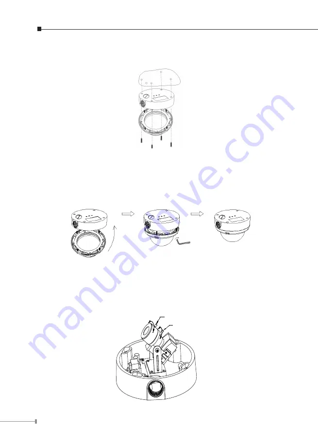
2. Set  the  mounting  base  onto  the  wall  or  ceiling  and  center  it  over  the  mounting 

hole, using the supplied four retaining screws to secure the main body. 

3. Set the proper image by moving the IP camera body (some model may limit the 

PCB  board  to  180°  rotational  adjustment)  and  set  the  focus  by  turning  the  lens 
to the left or right direction. 

4. When  the  IP  camera  focus  adjustment  has  been  completed,  use  the  provided 

L-wrench to fasten the tamper-resistant housing to the main body.

5. Vari-Focal operation guide:

Once  the  picture  appears  on  the  monitor,  open  the  cover  and  adjust  the  lens 
wrench  to 

“NEAR



FAR”

,  get  the  view  zoom  that  you  desire,  and  then  adjust 

the  focus  wrench  of  the  lens  to  obtain  the  best  picture.  After  adjustment,  tighten 
both wrenches.

Zoom Adjustment

Focal Adjustment

NEAR

FAR

WIDE

TELE

Summary of Contents for ICA-H312

Page 1: ...H 264 Internet Camera ICA HM230 ICA H312 ICA H651 ICA HM130 ICA HM135 ICA HM350 Quick Installation Guide Version 1 0...

Page 2: ...r Speed Dome Internet Camera 9 2 3 1 ICA H651 Package Content 9 2 3 2 ICA H651 Physical Details 9 2 3 3 ICA H651 Installation 10 2 4 ICA HM130 H 264 Mega Pixel Dome Internet Camera 12 2 4 1 ICA HM130...

Page 3: ...another This state of art design is considerable to fit in various network environments 1 1 Before Installation Before installation please be sure to read this quick installation guide and user s man...

Page 4: ...mera 2 1 1 ICA HM230 Package Content IP Camera Unit x 1 Power Adapter x 1 Camera Mount Kit x 1 User s Manual CD ROM x 1 Quick Installation Guide x 1 Note If any of the above items are missing please c...

Page 5: ...ter simultaneously 3 RJ 45 LAN Socket The LAN socket is a RJ 45 connector for connections to 10 100Base TX Fast Ethernet cabling This Ethernet port built N Way protocol can detect or negotiate the tra...

Page 6: ...chors and screws 2 Fix the IP camera to L type bracket with the two supplied screws 3 Connect the LAN cable to a switch or hub When this switch hub is a PoE device you can ignore the next step 4 Conne...

Page 7: ...e are two LEDs embedded LAN LED green color This LED will be flashing while network accessing via Ethernet Power LED orange color This LED is used to indicate whether DC power is on or not RS485 DI DO...

Page 8: ...internet camera Otherwise the product may be damaged 2 The power adapter is unnecessary when internet camera is connected to a PoE switch Otherwise the product may be damaged when internet camera is...

Page 9: ...te If any of the above items are missing please contact your dealer immediately 2 3 2 ICA H651 Physical Details 1 RJ45 LAN socket Connect to PC or Hub Switch For connects to 10Base T Ethernet or 100Ba...

Page 10: ...onitor or VCR 4 AC 24V in The input power is AC 24V 5 MIC in audio in Connect a microphone input source to the IP camera 6 Line out audio out Connect a loud speaker to the IP camera This function is f...

Page 11: ...as figure Note Due to the IP camera is heavy while installing be ware of object falling that could injure workers below or damage the IP camera permanently Ceiling Mount 1 Disassemble the Outdoor Fla...

Page 12: ...x 1 Power Adapter x 1 Mount Screw x 4 User s Manual CD ROM x 1 Quick Installation Guide x 1 Note If any of the above items are missing please contact your dealer immediately 2 4 2 ICA HM130 Physical D...

Page 13: ...sensor in and alarm out devices Cable for I O connectors Name Cable Color Function DC 12V Brown White DC 12V 50mA maximum GND Blue White GND D Purple White RS485 data D Gray RS485 data DI Green White...

Page 14: ...may be damaged when internet camera is connected to a PoE switch and power adapter simultaneously 5 MIC in audio in Connect a microphone to the IP camera 6 Line out audio out Connect a loud speaker t...

Page 15: ...r adapter 7 Done 2 5 ICA HM135 H 264 Mega Pixel 20M IR Vandal Proof IP Dome 2 5 1 ICA HM135 Package Content IP Camera Unit x 1 Power Adapter x 1 Mount Screw x 4 User s Manual CD ROM x 1 Quick Installa...

Page 16: ...sensor in and alarm out devices Cable for I O connectors Name Cable Color Function DC 12V Brown White DC 12V 50mA maximum GND Blue White GND D Purple White RS485 data D Gray RS485 data DI Green White...

Page 17: ...onnected to a PoE switch Otherwise the product may be damaged when internet camera is connected to a PoE switch and power adapter simultaneously 5 MIC in audio in Connect a microphone to the IP camera...

Page 18: ...the lens to the left or right direction 4 When the IP camera focus adjustment has been completed use the provided L wrench to fasten the tamper resistant housing to the main body 5 Vari Focal operatio...

Page 19: ...de x 1 Note If any of the above items are missing please contact your dealer immediately 2 6 2 ICA HM350 Physical Details 1 RJ 45 LAN socket Connect to PC or Hub Switch For connect to 10Base T Etherne...

Page 20: ...GND D Purple White RS485 data D Gray RS485 data DI Green White Digital signal input DO Orange White Digital signal output 3 Reset Button This button is used to restore the all factory default settings...

Page 21: ...e into RJ 45 connector Connect an Ethernet cable to the LAN socket located on the IP Camera s back panel and attach it to the network 3 Connect RS485 D and D if you need to control PT scanner 4 Connec...

Page 22: ...hen the welcome web page appear please click your IP camera name on the IP camera list Then click the PLANET IPWizard II hyperlink to start the PLANET IPWizard II Search function Press Search button P...

Page 23: ...now open your web browser and key in http 192 168 0 20 in the address bar of you web browser to logon IP Camera s web configuration page 2 Power Line Frequency If you found the video image is flash y...

Page 24: ...default IP Address 192 168 0 20 is already used by another device the other device must be turned OFF until the device is allocated a new IP Address during configuration Further Information This guid...

Reviews: