background image


Default VLANs 

The Managed Media Converter initially configures one VLAN, VID = 1, called 

"default."

 The factory default setting 

assigns all ports on the Managed Media Converter to the 

"default"

. As new VLAN are configured in Port-based mode, 

their respective member ports are removed from the 

"default."


4.5.1 VLAN Group 

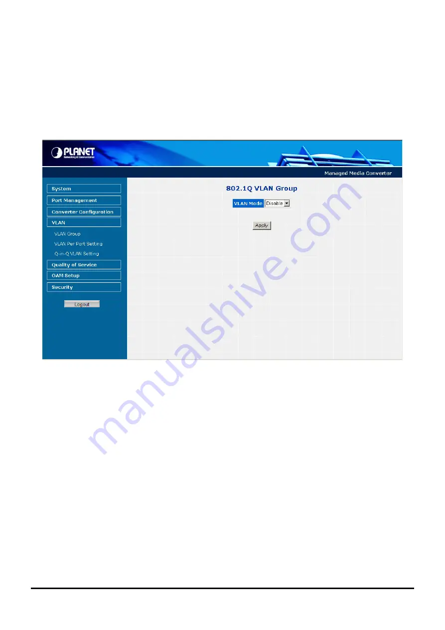
This function allows disable or enable the IEEE 802.1Q VLAN operation mode. Press the 

“Apply”

 button to save the 

current configuration of Managed Media Converter. The screen in 

Figure 4-27 & 4-28 

appears and 

Table 4-9

 describes the 

VLAN Group object of Managed Media Converter. 


Figure 4-27 

VLAN Group Web Page screen 


-37- 

Summary of Contents for GT-902

Page 1: ...User s Manual GT 902 GT 902S GT 905A GT 906A15 GT 906B15 GT 906A60 GT 906B60 GT 906A80 GT 906B80 10 100 1000Base T to 1000Base SX LX Managed Media Converter ...

Page 2: ...ate your comments and suggestions FCC Warning This equipment has been tested and found to comply with the limits for a Class A digital device pursuant to Part 15 of the FCC Rules These limits are designed to provide reasonable protection against harmful interference when the equipment is operated in a commercial environment This equipment generates uses and can radiate radio frequency energy and i...

Page 3: ...and electronic equipment should understand the meaning of the crossed out wheeled bin symbol Do not dispose of WEEE as unsorted municipal waste and have to collect such WEEE separately Revision PLANET Managed Gigabit Ethernet Media Converter User s Manual FOR MODELS GT 902 GT 902S GT 905A GT 906A15 GT 906B15 GT 906A60 GT 906B60 GT 906A80 GT 906B80 REVISION 1 1 June 2010 Part No 2080 AA3450 003 ...

Page 4: ...NAGEMENT METHODS 12 3 2 1 Web Management 13 3 2 2 SNMP Management 13 3 2 3 PLANET Smart Discovery Utility 14 3 2 4 Login the Managed Media Converter 15 4 WEB MANAGEMENT 16 4 1 MAIN MENU 16 4 2 SYSTEM 17 4 2 1 System Information 17 4 2 2 IP Configuration 18 4 2 3 Password Setting 19 4 2 4 Firmware Upgrade 20 4 2 5 SNMP Management 24 4 2 6 Factory Default 26 4 2 7 System Reboot 27 4 3 PORT MANAGEMEN...

Page 5: ...802 3ah Setup 49 4 7 5 802 3ah Loop Back Test 50 4 8 SECURITY 52 4 9 LOGOUT 53 5 TROUBLESHOOTING 54 APPENDIX A NETWORKING CONNECTION 55 A 1 DEVICE S RJ 45 PIN ASSIGNMENTS 55 A 2 RJ 45 CABLE PIN ASSIGNMENT 55 A 3 FIBER OPTICAL CABLE CONNECTION PARAMETER 56 A 4 POWER INFORMATION 57 A 5 AVAILABLE MODULES 57 5 ...

Page 6: ...ule is not bundled with in the package 1 2 How to Use This Manual The Managed Media Converter User s Manual is structured as followings Section 2 Hardware Installation It explains the functions of Managed Media Converter and how to install the Managed Media Converter Section 3 Media Converter Management It contains information about how to manage the Managed Media Converter Section 4 Web Managemen...

Page 7: ...d duplex mode setting flow control setting and Ingress Egress bandwidth control setting converter configuration that include maximum packet length setting Broadcast Multicast Unicast storm control setting 16 IEEE 802 1Q VLAN groups support and powerful Q in Q VLAN function Quality of Service QoS TS 1000 IEEE 802 3ah OAM function and TCP UDP filter function It supports standard Simple Network Manag...

Page 8: ...m single mode fiber 9μm 125μm on GT 906A80 B80 1000Base T 2 pair Cat 5 5e 6 UTP cable up to 100 meters Compacts size for working with PLANET MC family Media Chassis MC 700 1500 1500R 1500R48 Wall mountable hardware designed Built in IP Base Web interface for remote management Layer 2 Management Feature Store and Forward mechanism Built in Web operation interface for remote management and setup Man...

Page 9: ...LX Ports 1 x 10 100 1000Base T port 1 x 1000Base SX LX LX WDM port 1 x 1000Base SX LX SFP slot Copper Interface RJ 45 port Auto MDI MDI X Twisted Pair Optic Interface SC SFP WDM Optic Wavelength 850nm 1310nm TX 1310nm RX 1550nm TX 1550nm RX 1310nm Max 4 dBm 3 dBm 3 dBm 5 dBm Launch Power dBm Min 9 5 dBm 9 5dBm 9 dBm 0 dBm Receive Sensitivity 13 5 dBm 14 4 dBm 21 dBm 25 dBm Maximum Input power 18 d...

Page 10: ...Bm 0 dBm 2 dBm 2 dBm Receive Sensitivity 21 dBm 25 dBm 26 dBm 26 dBm Maximum Input power 2 dBm 2 dBm 1 dBm 1 dBm Twisted pair 10 20Mbps for Half Full Duplex 100 200Mbps for Half Full Duplex 2000Mbps for Full Duplex Speed Fiber optic 2000Mbps for Full Duplex Twisted pair 10Base T 2 pair UTP Cat 3 4 5 up to 100 m 100Base TX 2 pair UTP Cat 5 up to 100 m 1000Base T 4 pair STP Cat 5 up to 100m Cable Fi...

Page 11: ...e desktop or shelf Basic knowledge of networking is assumed Please read this chapter completely before continuing 2 1 GT 90X Front Panel The Front Panel of the Managed Media Converter consists of one 1000Base SX 1000Base LX mini GBIC SFP 1000Base LX WDM ports and one Auto Sensing 10 100 1000Mbps Ethernet RJ 45 Port Figure 2 1 2 2 2 3 shows a front panel of Managed Media Converter Figure 2 1 PLANET...

Page 12: ...he entire configuration will be erased when pressing the RESET button Press and release the RESET button shortly the device will be rebooted Press the RESET button more than 10 seconds the device will back to the factory default mode the entire configuration will be erased 2 1 2 GT 90X Rear Panel The rear panel of the Managed Media Converter indicates one DC jack which accepts input power with 5V ...

Page 13: ...tand alone Installation To install a Managed Media Converter stand alone on a desktop or shelf simply complete the following steps Step 1 Turn off the power of the device station in a network to which the Managed Media Converter will be attached Step 2 Ensure that there is no activity in the network Step 3 Attach fiber cable from the Managed Media Converter to the fiber network TX RX must be paire...

Page 14: ...o install GT 905A with 1000Base SX LX SFP simply complete the following steps Step 1 Precede with the steps 4 and steps 5 of session 2 2 1 Stand alone Installation to connect the network cabling and supply power to your converter Step 2 Slot in the 1000Base SX LX SFP Make sure both side of the SFP transceiver are with the same media type for example 1000Base SX 220m 550m to 1000Base SX 220m 550m 1...

Page 15: ...ert a Managed Media Converter into an available slot Step 3 Attach a rack mount bracket to each side of the Chassis with supplied screws attached to the package Step 4 After the brackets are attached to the chassis use suitable screws to securely attach the brackets to the rack as shown in Figure 2 6 Step 5 Precede with the steps 4 and steps 5 of session 2 2 1 Stand alone Installation to connect t...

Page 16: ...Figure 2 6 Mounting the Chassis in a Rack 11 ...

Page 17: ...dia Converter management The GT 90X provides a simply WEB browser interface Using this interface you can perform various Managed Media Converter configuration and management activities including System Port Management Converter Configuration VLAN Quality of Service OAM Setup Security Logout Please refer to the following Chapter 4 for more details 3 2 Management Methods The way to manage the GT 90X...

Page 18: ...ault IP address then the manager PC should be set at 192 168 0 x where x is a number between 1 and 254 except 100 and the default subnet mask is 255 255 255 0 Use Internet Explorer 5 0 or above Web browser enter default IP address http 192 168 0 100 After entering the username and password default user name and password is admin in login screen then the Web main screen appears 3 2 2 SNMP Managemen...

Page 19: ...overy Utility 1 Deposit the Planet Smart Discovery Utility in administrator PC 2 Run this utility and the following screen appears Figure 3 1 Planet Smart Discovery Utility Screen Notice If there are two LAN cards or above in the same administrator PC choose different LAN card by use the Select Adapter tool 3 Press Refresh button for list current connected devices in the discovery list the screen ...

Page 20: ... shutdown the planet Smart Discovery Utility 3 2 4 Login the Managed Media Converter Before you start configure the Managed Media Converter please note the Managed Media Converter is configured through an Ethernet connection make sure the manager PC must be set on same the IP subnet address For example the default IP address of the Managed Media Converter is 192 168 0 100 then the manager PC shoul...

Page 21: ...n screen the configurable management functions are shown as below System Provide System configuration of Managed Media Converter Explained in section 4 2 Port Management Provide Port Management configuration of Managed Media Converter Explained in section 4 3 Converter Configuration Provide Converter configuration of Managed Media Converter Explained in section 4 4 VLAN Provide VLAN configuration ...

Page 22: ...wing fields MAC Address Specifies the MAC address of Managed Media Converter Software Version The current software version running on the Managed Media Converter IP Address The current IP Address of Managed Media Converter the default IP Address is 192 168 0 100 Subnet Mask The current Subnet Mask of Managed Media Converter the default Subnet Mask is 255 255 255 0 Gateway The current gateway of Ma...

Page 23: ...100 Subnet Mask Allow assigning a new subnet mask for the Managed Media Converter the factory default subnet mask is 255 255 255 0 Gateway Allow assigning a new gateway for the Managed Media Converter the factory default gateway is 192 168 0 254 Description Allow to input a new description for the Managed Media Converter up to maximum 32 characters allow Apply button Press Apply button for save cu...

Page 24: ...ministrator to secure Web login The screen in Figure 4 4 4 5 appears and Table 4 3 describes the Password Setting object of Managed Media Converter Figure 4 4 Password Setting Web page screen Figure 4 5 Password Setting Successful Web page screen 19 ...

Page 25: ...the field The maximum length is 16 characters Confirm This confirms the new password The password entered into this field must be exactly the same as the password entered in the Password field Apply button Press Apply button for save current configuration of Managed Media Converter Table 4 3 Descriptions of the Password Setting Web Page Screen Objects 4 2 4 Firmware Upgrade This function provides ...

Page 26: ...e screen in Figure 4 7 appears Figure 4 7 Firmware Upgrade Web page screen After find the firmware location from administrator PC press Upgrade button to start the firmware upgrade process The screen in Figure 4 8 4 9 appears Figure 4 8 Firmware Upgrade Web page screen 21 ...

Page 27: ...When firmware upgrade process is completed then the following screen appears please click here to re login the Managed Media Converter with latest firmware and the screen in Figure 4 10 4 11 appears Figure 4 10 Firmware Upgrade Web page screen 22 ...

Page 28: ...Figure 4 11 Login Web page screen 23 ...

Page 29: ... SNMP Read Community Allow input the characters for SNMP Read Community up to maximum 16 characters allow SNMP Write Community Allow input the characters for SNMP Write Community up to maximum 16 characters allow System Name Allow input the characters for System Name up to maximum 16 characters allow System Location Allow input the characters for System Location up to maximum 16 characters allow C...

Page 30: ...cutes Warm Start operation the administrator PC SNMP Trap Destination will receive a Warm Start Trap Login Fail When Web login fail situation appears on Managed Media Converter the administrator PC SNMP Trap Destination will receive a Login Fail Trap Link Up When TP or Fiber port connection is build up the administrator PC SNMP Trap Destination will receive a Link Up Trap Trap Event Link Down When...

Page 31: ...lt This function provides Factory Default function of the Managed Media Converter and the screen in Figure 4 14 4 15 4 16 appears Figure 4 14 Factory Default Web page screen Figure 4 15 Factory Default Web page screen 26 ...

Page 32: ... Login Web page screen 4 2 7 System Reboot This function provides System Reboot function of the Managed Media Converter and the screen in Figure 4 17 4 18 4 19 appears Figure 4 17 System Reboot Web page screen 27 ...

Page 33: ...Figure 4 18 System Reboot Web page screen Figure 4 19 Login Web page screen 28 ...

Page 34: ...ion Web page includes the following configurable data Port Indicate the TP port and Fiber port Link Displays the current connection speed and duplex mode of TP or Fiber port Mode Allow configuring the TP or Fiber port speed and operation mode Draw the menu bar to select the mode TP Port Auto Speed Setup Auto negotiation 1000 Full Force sets 1000Mbps Full Duplex mode 100 Full Force sets 100Mbps Ful...

Page 35: ...ns are No Limit 512K 1M 2M 4M 8M 10M 50M 100M 500M Default mode No Limit The Ingress Rate Limit configuration field as show in Figure 4 21 Egress Shaping The value of outbound traffic limitation in kilobit per second kbps The available options are No Limit 512K 1M 2M 4M 8M 10M 50M 100M 500M Default mode No Limit The Egress Shaping configuration field as show in Figure 4 22 Apply button Press this ...

Page 36: ...Figure 4 21 Port Configuration Ingress Rate Limit Web Page screen Figure 4 22 Port Configuration Egress Shaping Web Page screen 31 ...

Page 37: ...age includes the following configurable data Port Indicate the TP port and Fiber port Link Status Displays the current link status of TP and Fiber port Duplex Mode Displays the current duplex mode of TP and Fiber port Flow Control Displays the current Flow Control status of TP and Fiber port Speed Displays the current speed mode of TP and Fiber port Auto Negotiation Displays the current Auto negot...

Page 38: ...ber port detail Statistics press the Clear button to clear current counter information Press the Refresh button to renew the screen the screen in Figure 4 24 4 25 appears Figure 4 24 Port Statistics Web Page screen Figure 4 25 Port Statistics Web Page screen 33 ...

Page 39: ...ble options are 1518 bytes 2048 bytes and 16K bytes Default mode is 16K bytes Loop Detection Provide Disable or enable the Loop detection function Default mode is Disable Loop Status Displays the Loop Detection status Broadcast Storm Control Provide Disable or enable the Broadcast Storm Control function Default mode is Disable Multicast Storm Control Provide Disable or enable the Multicast Storm C...

Page 40: ...er tagging or untagging The untagging feature of IEEE 802 1Q VLAN allows VLAN to work with legacy switches that don t recognize VLAN tags in packet headers The tagging feature allows VLAN to span multiple 802 1Q compliant switches through a single physical connection and allows Spanning Tree to be enabled on all ports and work normally Any port can be configured as either tagging or untagging The ...

Page 41: ...ch all ports are then assigned to a default VLAN with a PVID equal to 1 Untagged packets are assigned the PVID of the port on which they were received Forwarding decisions are based upon this PVID in so far as VLAN are concerned Tagged packets are forwarded according to the VID contained within the tag Tagged packets are also assigned a PVID but the PVID is not used to make packet forwarding decis...

Page 42: ...ed in Port based mode their respective member ports are removed from the default 4 5 1 VLAN Group This function allows disable or enable the IEEE 802 1Q VLAN operation mode Press the Apply button to save the current configuration of Managed Media Converter The screen in Figure 4 27 4 28 appears and Table 4 9 describes the VLAN Group object of Managed Media Converter Figure 4 27 VLAN Group Web Page...

Page 43: ...nd the available options are 1 to 4094 TP Provide assign TP port into VLAN Groups Member Fiber Provide assign Fiber port into VLAN Groups Apply button Press this button for save current configuration of Managed Media Converter Table 4 9 Descriptions of the VLAN Group Web Page Screen Objects Notice When change the Management VLAN Group setting please assure the TP or fiber port that connect to admi...

Page 44: ...ndicate the TP port and Fiber port Egress Link Type Provide Egress Link Type options for TP port and Fiber port the available options are UnTag Tag ByPass Default mode is UnTag PVID Provide PVID assign for TP port and Fiber port the available options are 1 to 4094 Default mode is 1 to 16 Accept Frame Type Provide define the Accept Frame Type and the available options are All Tagged Only Default mo...

Page 45: ...naged Media Converter The screen in Figure 4 30 appears and Table 4 11 describes the Q in Q VLAN setting object of Managed Media Converter Figure 4 30 Q in Q VLAN setting Web Page screen The Q in Q VLAN setting Web page includes the following configurable data Q in Q Enable Provide disable or enable the Q in Q VLAN function Default mode is Disable Q in Q direction Provide two directions for Q in Q...

Page 46: ... traffic by Classifying traffic based on packet attributes Assigning priorities to traffic for example to set higher priorities to time critical or business critical applications Applying security policy through traffic filtering Provide predictable throughput for multimedia applications such as video conferencing or voice over IP by minimizing delay and jitter Improve performance for specific typ...

Page 47: ...w in Figure 4 33 IP DSCP Priority The IP DSCP Priority field as show in Figure 4 34 Default mode is Disable Scheduling Provide two scheduling method for Quality of Service the available options are Strict Priority Weighted Round Robin 16 8 4 1 Default mode is Strict Priority Apply button Press this button for save current configuration of Managed Media Converter Table 4 12 Descriptions of the Qual...

Page 48: ...Figure 4 33 IP Address Priority Web Page screen Figure 4 34 IP DSCP Priority Web Page screen 43 ...

Page 49: ...tup Web page includes the following configurable data TS 1000 OAM State Provide disable or enable the TS 1000 OAM operation mode Default mode is Disable TS 1000 Mode Provide two TS 1000 modes for operation the available options are Terminal Center Default mode is Terminal Link Transparent Provide disable or enable the Link Transparent function Default mode is Disable Link Transparent Result Displa...

Page 50: ...notification 1 Terminal Media Converter notifies the center Media Converter autonomously with a status notification indication if any change occurs in the status monitored internally by the terminal Media Converter 2 Center Media Converter if support Option A notifies the terminal Media Converter autonomously with a status notification indication if any change occurs in the status monitored intern...

Page 51: ...Figure 4 37 GT 90x Remote TS 1000 OAM Setup Web Page screen Notice Please use the PLANET GT 80x and GT 90x as the Remote device 46 ...

Page 52: ...e and terminal Media Converter loop back the frames Test frame can be generated from central Media Converter s UTP port Out Band or from central Media Converter In Band automatically 4 Center Media Converter check the loop back test result after sending all test frames 5 Instruct the central Media Converter to end loop back test This function provides TS 1000 Loop Back Test of Managed Media Conver...

Page 53: ...Default is 16 Apply button Press this button for save current configuration of Managed Media Converter Refresh button Press Refresh button to refresh current status TS 1000 Loop Back Test Result Result Display the TS 1000 Loop Back Test Result Fail or Pass Result counter Display the value of Counter Result Table 4 14 Descriptions of the TS 1000 Loop Back Test Web Page Screen Objects Notice Please ...

Page 54: ...nt configuration of Managed Media Converter The screen in Figure 4 39 appears and Table 4 15 describes the 802 3ah Setup object of Managed Media Converter Figure 4 39 802 3ah Setup Web Page screen The 802 3ah Setup Web page includes the following configurable data 802 3ah OAM State Provide disable or enable the 802 3ah OAM State function Default mode is Enable 802 3ah OAM Mode Allow to choose Acti...

Page 55: ...ion between two Media Converter devices To assure the Remote 802 3ah function can work correctly This function provides 802 3ah Loop Back Test of Managed Media Converter Press the Apply button to run 802 3ah Loop Back Test and see the 802 3ah Loop Back Test Result of Managed Media Converter also press the Refresh button to renew the Web screen The screen in Figure 4 40 appears and Table 4 16 descr...

Page 56: ...ngth and the available options is 60 to 1514 Default is 60 Apply button Press this button for save current configuration of Managed Media Converter Refresh button Press Refresh button to refresh current status 802 3ah Loop Back Test Result Result Display the 802 3ah Loop Back Test Result Fail or Pass Table 4 16 Descriptions of the 802 3ah Loop Back Test Web Page Screen Objects Notice 1 The 802 3ah...

Page 57: ...available range is 1 to 16 Action Provide Deny or Permit options and default mode is Permit Egress Port Provide choose TP or Fiber as Egress Port Default mode is TP Packet Type Provide IPv4 and Non IPv4 protocol for further setting L4 Protocol Provide IPv4 and Non IPv4 protocol for further setting IPv4 TCP Any FTP 21 HTTP 80 UDP Any TFTP 69 Non IPv4 Any ARP 0x0806 IPX 0X8137 Current List Display c...

Page 58: ...f Managed Media Converter when the Are you sure to logout pop window appears press the OK button to logout Web page of Managed Media Converter The screen in Figure 4 42 4 43 appears Figure 4 42 Logout Web Page screen Figure 4 43 Login Web Page screen 53 ...

Page 59: ...T port link LED is lit but the traffic is irregular Solution Check that the attached device is not set to dedicate full duplex Some devices use a physical or software switch to change duplex modes Auto negotiation may not recognize this type of full duplex setting Why the device doesn t connect to the network Solution Check the LNK ACT LED on the Managed Media Converter Try another port on the con...

Page 60: ... BI_DD 6 BI_DB BI_DA 7 BI_DD BI_DC 8 BI_DD BI_DC 10 100Mbps 10 100Base TX RJ 45 Connector pin assignment Contact MDI Media Dependant Interface MDI X Media Dependant Interface Cross 1 Tx transmit Rx receive 2 Tx transmit Rx receive 3 Rx receive Tx transmit 4 5 Not used 6 Rx receive Tx transmit 7 8 Not used A 2 RJ 45 cable pin assignment 21 3 6 1 2 3 6 21 3 6 The standard RJ 45 receptacle connector ...

Page 61: ...our connected cables are with same pin assignment and color as above picture before deploying the cables into your network A 3 Fiber Optical Cable Connection Parameter The wiring details are as below Fiber Optical patch Cables Standard Fiber Diameter micron Modal Bandwidth MHz km Max Distance meters 1000Base SX Multi mode 62 5 62 5 50 50 100 200 400 500 220 275 500 550 Multi mode 62 5 50 50 5 4 5 ...

Page 62: ...es The following list the available Modules for GT 905A MGB GT SFP Port 1000Base T mini GBIC module MGB SX SFP Port 1000Base SX mini GBIC module MGB LX SFP Port 1000Base LX mini GBIC module MGB L30 SFP Port 1000Base LX mini GBIC module 30KM MGB L50 SFP Port 1000Base LX mini GBIC module 50KM MGB L70 SFP Port 1000Base LX mini GBIC module 70KM MGB L120 SFP Port 1000Base LX mini GBIC module 120KM MGB ...

Page 63: ...tates relating to Electromagnetic Compatibility Directive on 89 336 EEC For the evaluation regarding the EMC the following standards were applied Emission EN 55022 1994 A1 1995 A2 1997 Harmonic EN 61000 3 2 2000 Flicker EN 61000 3 3 1995 A1 2001 Immunity EN 55024 1998 ESD IEC 61000 4 2 2001 RS IEC 61000 4 3 1995 EFT Burst IEC 61000 4 4 1995 Surge IEC 61000 4 5 1995 CS IEC 61000 4 6 1996 Magnetic F...

Reviews: