background image

User’s Manual of FGSW-4840S


32 

5. TROUBLESHOOTING 


This chapter contains information to help you solve problems. If the Switch is not functioning properly, make sure the 
Ethernet Switch was set up according to instructions in this manual. 

The Link LED is not lit 

Solution:


Check the cable connection and its quality. 


Some stations cannot talk to other stations located on the other port  


Solution: 

Please check the VLAN, port trunking function that may introduce this kind of problem. 
The address table may contain older information than of the address table of that node. Please power down to refresh the 
address information. 


Performance is bad 

Solution: 

Check the full duplex status of the partner Switch or device. The partner switch is run at full duplex and the Switch runs 
at Auto-Negotiation (half-duplex mode), then the performance will be poor. 

Why the Switch doesn’t connect to the network 

Solution: 


Check the LNK/ACT LED on the Switch 

         Try another port on the Switch 
         Make sure the cable is installed properly 


  Make sure the cable is the right type 


        Turn off the power. After a while, turn on power again 

Why the LNK/ACT LED of SFP-Mini-GBIC interfaces is not lit? 

Solution: 

           Check the fiber connection  
           Assure use the correct fiber cable for multi-mode and single-mode 
           Check the port setting of this Switch 

Summary of Contents for FGSW-4840S

Page 1: ...User s Manual FGSW 4840S 48 Port 10 100Mbps 4G Web Smart Ethernet Switch...

Page 2: ...iate your comments and suggestions FCC Warning This equipment has been tested and found to comply with the limits for a Class A digital device pursuant to Part 15 of the FCC Rules These limits are des...

Page 3: ...5 1 Port Parameter 11 3 5 2 Port Statistic 12 3 5 3 Port Status 13 3 5 4 Rate Limiting 14 3 5 5 Storm Control 15 3 5 6 Port Description 16 3 6 NETWORK SETTING 17 3 6 1 Switch IP Address 17 3 6 2 Stati...

Page 4: ...4 APPENDIX A 33 A 1 SWITCH S RJ 45 PIN ASSIGNMENTS 33 A 2 10 100MBPS 10 100BASE TX 33 A 3 RJ 45 CABLE PIN ASSIGNMENT 33...

Page 5: ...n 5 Troubleshooting It contains troubleshooting guide of FGSW 4840S Appendix A It contains cable information of FGSW 4840S In the following section the term Switch means the FGSW 4840S term of switch...

Page 6: ...Address Table 8K entries Flow Control Back pressure for half duplex IEEE 802 3x Pause Frame for full duplex Dimensions mm 440 x 260 x 44 mm 1U height Weight 3 4kg Power Requirement 100 240V AC 50 60 H...

Page 7: ...f connection to any Ethernet device without requiring special straight or crossover cables The FGSW 4840S also provides 2 SFP Mini GBIC interfaces for fiber extension to uplink to a server or a networ...

Page 8: ...Smart Ethernet Switch and make connections to the Switch Please read the following topics and perform the procedures in the order being presented PLANET FGSW 4840S Web Smart Ethernet Switch do not nee...

Page 9: ...one side of the Switch Figure 2 3 Attaching the brackets to the FGSW 4840S Caution You must use the screws supplied with the mounting brackets Damage caused to the parts by using incorrect screws woul...

Page 10: ...Setting Network Setting VLAN Setting Port Trunking Priority Setting Port Mirroring Virtual Cable Test 3 2 Login the Switch Before you start configure the FGSW 4840S please note the FGSW 4840S is conf...

Page 11: ...User s Manual of FGSW 4840S 7 3 3 Main Menu After entering the password the main screen appears the main screen displays the Switch status The screen in Figure 3 2 appears Figure 3 2 Web Main screen...

Page 12: ...em Name System Location Contact Information and Run time The screen in Figure 3 3 appears Figure 3 3 System information screen 3 4 2 File Transfer This function allows upgrade system backup and restor...

Page 13: ...em upgrading screen Figure 3 6 configuration backup screen Figure 3 7 configuration loading screen 3 4 3 Reboot Reset This function provides administrator to reboot or reset to default See the screen...

Page 14: ...the setting The screen in Figure 3 9 appears Figure 3 9 User screen Note Up to 16 characters is allowed for the password After change the default password if you forget the password Please press and r...

Page 15: ...enus Port Parameter Port Statistic Port Status Rate Limiting Storm Control Port Description 3 5 1 Port Parameter This function allows displaying each port s parameter like Port status Port Security Fl...

Page 16: ...ll of the port security to be enable which will cause to not able to manage the Switch Flow control This setting determines whether or not the Switch will be handling flow control Set Flow Control to...

Page 17: ...isplay the Port Status Speed Duplex Mode and Flow control The Port Status in the screen displays the current connection speed and duplex mode else this function will show Linkdown when the port is dis...

Page 18: ...belongs to Trunk members do not support rate limiting Ingress Limiting Enable or disable the ingress rate limiting Ingress Bandwidth Value of the ingress bandwidth Egress Limiting Enable or disable t...

Page 19: ...k If the port is a Trunk member it indicates which Trunk it belongs to In the parameters field it list the parameters of the Trunk which it belongs to and can t be modified here you can configure the...

Page 20: ...User s Manual of FGSW 4840S 16 3 5 6 Port Description This function provides administrator can type word to indicate the port The screen in Figure 3 15 appears Figure 3 15 Port description screen...

Page 21: ...sponding switch port The static MAC address won t age which differs from the dynamic MAC address The static MAC address table entry is always valid before it is deleted Supposing an entry whose MAC ad...

Page 22: ...source address for traffic entering the switch When the destination address for inbound traffic is found in the database the packets intended for that address are forwarded directly to the associated...

Page 23: ...ual of FGSW 4840S 19 Figure 3 19 Dynamic binding screen 3 6 5 Bound MAC Address This page shows the MAC addresses bound to the switch ports The screen in Figure 3 20 appears Figure 3 20 Bound MAC Addr...

Page 24: ...m the MAC address table This process is called aging and the specified time length referred above is called aging time The aging time ranges from 0 to 3825 seconds the default value is 300 seconds Dyn...

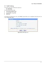
Page 25: ...menus VLAN Mode The VLAN mode had three modes z Port VLAN Port Based VLAN z Tag VLAN 802 1Q Tag VLAN z MTU VLAN This function group individual ports into a small Virtual network of their own to be ind...

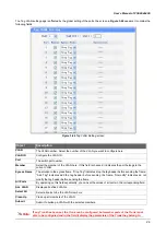
Page 26: ...e If this field is checked it indicates the port belongs to the current VLAN Member Description Displays the user defined port description ALL VLAN Displays all defined VLANs Select All Select all por...

Page 27: ...ag frame from the port the switch will assign a tag to the frame using the PVID of the port as its VID Untag Frame The solution to the untag frame received Drop will drop the frame and Pass will trans...

Page 28: ...gure the VLAN ID Port The switch port number Member Select the member of the VLAN here If this field is checked it indicates the port belongs to the current VLAN Egress Frame The solution to the egres...

Page 29: ...with each of the other ports Each VLAN contains two ports the uplink port and one of the other ports in the switch so the uplink port can communicate with any other ports but other ports can t communi...

Page 30: ...ng The priority setting of the switch can be set to Disable Port Based or IEEE802 1p The priority setting menus include the tree sub menus Priority mode Port Based priority Port Default priority 802 1...

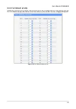
Page 31: ...ased priority The Switch have four priority classes lowest lower higher and highest in port based priority mode The priority class of the port is applied to the all packets entering from the port The...

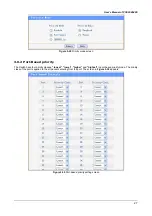
Page 32: ...1p priority mode is configured when the switch port receives an untagged frame a frame without priority tag the port s default priority tag will be inserted into the frame before any other process The...

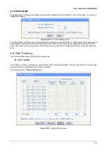
Page 33: ...reen 3 10 Port Mirroring The System setting menus include the tree sub menus Port Mirroring Port mirroring monitors and mirrors network traffic by forwarding copies of incoming and outgoing packets fr...

Page 34: ...rtual Cable Test The Cable Test screen see figure 3 34 shows you results from performance tests on copper cables The maximum cable length that can be tested is 120 meters Cables are tested when the po...

Page 35: ...internal buffer do the complete error checking before transmission Therefore no error packets occurrence it is the best choice when a network needs efficiency and stability The Ethernet Switch scans t...

Page 36: ...ble of that node Please power down to refresh the address information Performance is bad Solution Check the full duplex status of the partner Switch or device The partner switch is run at full duplex...

Page 37: ...the crossover function within a twisted pair cable or at a wiring panel while not expressly forbidden is beyond the scope of this standard A 2 10 100Mbps 10 100Base TX RJ 45 Connector pin assignment C...

Page 38: ...d The following shows the pin allocation and color of straight cable and crossover cable connection Figure A 1 Straight Through and Crossover Cable Please make sure your connected cables are with same...

Reviews: