Plane-Power R1224 Installation Instructions Manual Download Page 28

R1224 Regulator
Installation Instruction

12-1001


      24-30-01

Rev. M

: 01 Dec. 2021 


Page: 6-5


© 2021 - Hartzell Engine Technologies - All rights reserved


WARNING:


TO PREVENT DAMAGE TO AIRCRAFT OR UNIT, READ AND UNDERSTAND ALL 


INSTRUCTIONS PRIOR TO APPLYING POWER TO UNIT. 


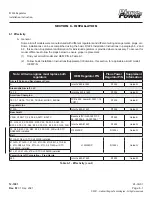
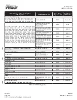
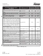
Current applications and specific regulator conversion/installation guides are available online at


www.planepower.aero or www.hartzell.aero


NOTE:

  Use appropriately sized M7928/5 splices, M7981/1, ring lugs, and MIL-W-22759/16 wire.

6.2   Single Engine 

A.  Installation

(1)  Remove existing regulator and solid-state over-voltage module (if installed).
(2)  Install  the regulator (R1224/R1224B/R1224J) in same location as regulator being replaced. If 

mounting holes do not align, add mounting holes as required using acceptable methods, techniques 

and practices such as those found in AC 43-13-1B and AC 43-13-2B.

(3)  Connect GRND terminal to aircraft ground. It is critical that the regulator ground is connected to 

airframe ground. Without this ground, the regulator and its internal overvoltage protection cannot 

function.

(4)   Connect the FLD terminal to the FIELD (brush) terminal of the alternator.  
(5)  Connect the ENABLE terminal to the regulator/field power source (the wire from the cockpit 

ALTERNATOR FIELD switch which is fed from a 7.5 max amp breaker). Note: In order for the over 

voltage protection circuit to operate the enable terminal must be connected to an operational circuit 

breaker. (In the event of an over-voltage condition the over-voltage protection circuit will cause the 

circuit breaker to trip removing all power from the regulating circuit.) Do not install the regulator in any 

aircraft that has an automatic resetting circuit breaker in the enable line.

(6)  If the regulator being replaced has a connection to the AUX terminal on the alternator, connect this wire 

to the AUX terminal. If not, install a jumper wire between AUX and ENABLE. Note: No connection to AUX 

terminal is necessary if an alternator out lamp is not installed.
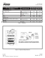
NOTE: 

  For superceded versions of the regulator (Rev B & previous) indicated by silver label, step 7  


does not apply and no sense terminal exists. Wiring of a ‘Sense’ terminal on these regulators  


will result in damage to the regulator.

(7) 

If an ALTERNATOR out lamp is installed in the aircraft and is to be actuated by the regulator, connect the 

negative wire of the lamp to the LAMP terminal of the regulator.

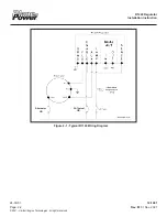
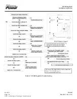
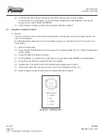
(8)  Remove the regulator cover and ensure that the internal jumper #1 and jumper #2 are set to the proper 

voltage for the aircraft system. Refer to Figure 6-1

.

(9) 

With the engine running and the alternator switch turned on, using a small screwdriver, set the regulator’s 

voltage adjustment so that the bus voltage, as measured at the ENABLE terminal is the desired value. 

Refer to aircraft maintenance manual or battery manufacturer’s data for proper voltage setting.

(10)  Reinstall the regulator cover.

6.3 


Multi-Engine

A.  Installation

(1)  For both regulators, perform steps 1 thru 10 of the Single Engine procedure, section 6.2.
(2)  Choose one regulator as the Master. It can be either. Connect the OUT terminal of the Master Regulator 

to the IN terminal of the other regulator.

Summary of Contents for R1224

Page 1: ...R1224 Regulator Installation Instruction 12 1001 24 30 01 Rev M 01 Dec 2021 Page i 2021 Hartzell Engine Technologies All rights reserved R1224 REGULATOR INSTALLATION INSTRUCTIONS P N 12 1001...

Page 2: ...s reserved Copyright 2021 Hartzell Engine Technologies LLC All rights reserved No part of this publication may be reproduced stored in a retrieval system or transmitted in any form or by any means ele...

Page 3: ...ed Airworthiness to Maintenance Instructions K 02 01 17 2 Added website reference to Master Drawing No 12 1001 L 04 30 18 ALL Revised to conform to iSpec 2200 Standard i Added HET standard cover page...

Page 4: ...R1224 Regulator Installation Instruction 24 30 01 12 1001 Page iv Rev M 01 Dec 2021 2021 Hartzell Engine Technologies All rights reserved THIS PAGE INTENTIONALLY LEFT BLANK...

Page 5: ...eviations 1 3 1 6 Definitions 1 4 1 7 Disposal 1 4 1 8 Storage 1 4 1 9 Serial number Identification 1 5 1 10 Warranties 1 5 SECTION 2 DESCRIPTION OF OPERATION 2 1 2 1 Description 2 1 2 2 Basic Compone...

Page 6: ...stallation Guide H 6 11 A General 6 11 6 12 Regulator Installation Guide I 6 12 A Prepare the replacement regulator 6 12 B Prepare the installation 6 12 C Replace the regulator 6 12 6 13 Regulator Ins...

Page 7: ...echsupport Hartzell aero Fax 1 334 386 5450 Web hartzell aero contact PlanePower is a trademark of Hartzell Engine Technologies LLC WARNING People who fly should recognize that there are various types...

Page 8: ...HE MINIMUM REQUIRED TO MEET CONTINUED AIRWORTHINESS BUT MAY BE SUPERSEDED BY MORE STRINGENT REQUIREMENTS AS PUBLISHED BY THE FAA AIRCRAFT ROTORCRAFT OR OTHER MANUFACTURERS THAT USE THESE COMPONENTS IN...

Page 9: ...replacement of the identified parts after a specified number of cycles or hours of use B Additions of or changes to any life limit for alternator components will be noted in theAirworthiness Limitati...

Page 10: ...pes of damages directly or indirectly resulting from the unauthorized use of this instruction for other than its stated purposes The liability for use of the authorized data herein for the maintenance...

Page 11: ...led on aircraft and tasks that should be accomplished in a properly equipped service facility F Maintenance tasks and subtasks are referenced in the instruction but will have no specific identificatio...

Page 12: ...ernator ATA Air Transport Association of America CB Circuit Breaker DIA Diameter FAA Federal Aviation Administration USA FIG Figure GAMA General Aviation Manufacturers Association HET Hartzell Engine...

Page 13: ...ption of a conductive path in an electrical circuit Will read infinite resistance VOLTAGE REGULATOR The voltage regulator controls system voltage by controlling the electrical circuit called the field...

Page 14: ...rough an authorized HET distributor in a manner prescribed by that specific distributor The affected regulator must be received by the factory fully assembled and not altered in any way for dispositio...

Page 15: ...THIS PAGE INTENTIONALLY LEFT BLANK R1224 Regulator Installation Instruction 24 30 01 12 1001 Page 1 6 Rev M 01 Dec 2021 2021 Hartzell Engine Technologies All rights reserved...

Page 16: ...ion 8 SENSE The R1224 regulator will apply power to the alternator s rotor when voltage at the SENSE terminal is below the regulator set point 2 3 Theory of Operation A Field drive The regulator sense...

Page 17: ...ure 2 1 Typical R1124 Wiring Diagram 5A Typical CB Alternator CB R1224 Regulator Installation Instruction 24 30 01 12 1001 Page 2 2 Rev M 01 Dec 2021 2021 Hartzell Engine Technologies All rights reser...

Page 18: ...REGULATOR GREAT CARE AND CAUTION MUST BE TAKEN TO AVOID HAZARDOUS SITUATIONS THE REGULATOR POSSESSES A HIGH ELECTRICAL CURRENT OUTPUT AND PRESENTS AN ELECTRICAL SHOCK HAZARD THAT CAN RESULT IN SERIOU...

Page 19: ...eshooting FIELD ALTERNATOR CB 1 AMP FUSE CB Call or email TECH SUPPORT for further instructions Phone 1 334 386 5400 option 2 E mail techsupport Hartzell aero Verify the R1224 Regulator is wired per a...

Page 20: ...rring B HET recommended maintenance and checks including TIS may be superseded by the aircraft or engine manufacturer s established time limits and schedules based on experience and or unique requirem...

Page 21: ...R1224 Regulator Installation Instruction 24 30 01 12 1001 Page 4 2 Rev M 01 Dec 2021 2021 Hartzell Engine Technologies All rights reserved THIS PAGE INTENTIONALLY LEFT BLANK...

Page 22: ...ircraft engine maintenance manuals and service instructions Alternatively Table 3 1 of Section 3 may be utilized to test the regulator for proper function R1224 Regulator Installation Instruction 12 1...

Page 23: ...THIS PAGE INTENTIONALLY LEFT BLANK R1224 Regulator Installation Instruction 24 30 01 12 1001 Page 5 2 Rev M 01 Dec 2021 2021 Hartzell Engine Technologies All rights reserved...

Page 24: ...regulators OEM Regulator P N Plane Power Regulator P N Supplement Information Aircraft Parts and Development Corp A InterAV 625 61623 R1224 Guide M Alexandria Aircraft LLC 14 19 InteraAv 625 61623 R1...

Page 25: ...TR182 188 188A 188B A188 A188A A188B Cessna 0750216 1 611001 0101 C611001 0102 C611001 0201 R1224 Basic Two Wire Cessna C611004 611005 0101 C611005 0102 C611005 0103 R1224 Guide B Four Wire Cessna C6...

Page 26: ...35 PA 28S 160 PA 28S 180 PA 28R 180 PA 28R 200 PA 12 PA 12S PA 18A Restricted PA 8A 135Restricted PA 18A 150 Restricted PA 30 InterAv 625 61623 R1224 Guide M PA 28 140 Cherokee Cruiser PA 28 150 PA 28...

Page 27: ...ulator P N Plane Power Regulator P N Supplement Information True Flight Holdings LLC AA 5 AA 5A AA 5B C6FF 10316BA D4FF 10316 BA R1224 Guide D AA 1B Prestolite FVR 4004 LW 11357 Wico X17990 X16300B R1...

Page 28: ...the over voltage protection circuit will cause the circuit breaker to trip removing all power from the regulating circuit Do not install the regulator in any aircraft that has an automatic resetting...

Page 29: ...age protection Splice together the power input and output wires that went to the overvoltage regulator Adjust voltage as necessary with engine running and alternator enabled 6 5 Regulator Installation...

Page 30: ...nd of the White OV Lamp wire and stow it safely The R1224 indicates Over Voltage and Low Voltage on a common lamp connected to R1224 5 11 Adjust voltage as necessary with engine running and alternator...

Page 31: ...ugged into the con nector on the regulator Use R1224B with the Plane Power 12 1016 Installation Aid Fig 6 2 Purchase the 12 1016 connector from Plane Power 1 Remove old regulator 2 Ensure that the R12...

Page 32: ...t each Red wire to 3 Enable of the corresponding R1224 7 Ensure that there is a jumper between 3 Enable and 4 Aux of each R1224B For R1224B Rev C and later Ensure there is a jumper between 3 Enable an...

Page 33: ...o 1 Ground of the corresponding R1224B 7 Connect each F wire to 2 Field of the corresponding R1224B 8 Connect each S or B wire to 3 Enable of the corresponding R1224B 9 Ensure that there is a jumper b...

Page 34: ...body and new ring lugs provided with the R1224 regulator 2 Unplug the wire connector from the aircraft plug 3 Connect the ring lugs to the R1224 regulator as shown below Red to ENABLE Blue to Field Wh...

Page 35: ...tion 1 Remove wire EL36A20 from the output side of the Alternator Control circuit breaker and connect it to the input side of the circuit breaker through a 1A fuse 2 Adjust voltage as necessary with e...

Page 36: ...V 2 Remove the factory jumper between SENSE and ENABLE 3 Remove the old regulators If the aircraft as equipped with Lamar Over voltage Relays you can remove them if you desire The R1224B has internal...

Page 37: ...removed 4 Remove the wires on both terminals of the ALTERNATOR switch on the aircraft panel Connect one terminal of the switch to the 5A breaker where the wire to Red Pos of the Interav OV Relay was c...

Page 38: ...eplace the regulator 1 Remove the old regulator and if present separate voltage protector 2 Remove the load resistor connected between the regulator and the aircraft bus or alternator output used with...

Page 39: ...R1224 Regulator Installation Instruction 24 30 01 12 1001 Page 6 16 Rev M 01 Dec 2021 2021 Hartzell Engine Technologies All rights reserved THIS PAGE INTENTIONALLY LEFT BLANK...

Reviews: