


SECTION 2 - DESCRIPTION OF OPERATION
2.1 Description
A.
The Plane Power R1224 Voltage Regulator is a solid-state voltage regulator with over-voltage protection, field
short (over current) protection, and reverse battery protection. The R1224 regulator is designed to be set up for
14 or 28 volt configurations.
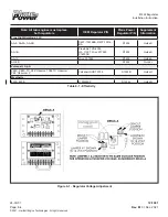
2.2 Basic Component Description
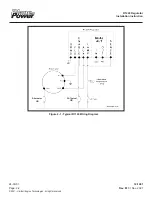
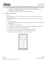
Refer to Figure 2-1
A. Connection Strip
(1)
GRND
- Aircraft ground
(2)
FLD
- Connects to one of the two alternator rotor brushes to engergize the rotor allowing the alternator to
generate power.
(3)
ENABLE
- Connects to the aircraft bus to supply electrical power to the regulator. Overvoltage
protection works by shorting the Enable pin to ground, tripping the the circuit breaker connected in
series.
(4)
AUX
- Senses the functional voltage of the alternator in order to trigger the LAMP circuit when a fault is
detected.
(5)
LAMP
- Will illuminate an indicator lamp in the case that a fault is detected by the regulator. The LAMP
circuit is rated to sink a maximum of 100mA of current.
(6)
OUT
- Used to control a second regulator in a dual alternator configuration.
(7)
IN
- Connection from the primary regulator (OUT) in a dual alternator configuration. If the signal from the
primary regulator is lost, the secondary regulator will resume independent operation.
(8)
SENSE
- The R1224 regulator will apply power to the alternator’s rotor when voltage at the SENSE
terminal is below the regulator set point.
2.3 Theory of Operation
A.
Field-drive:
The regulator senses the voltage at the SENSE terminal and provides power to the alternator
rotor. Energizing the rotor allows the alternator to generate power.
B.
Overvoltage Protection:
In the event that the voltage supplied to the ENABLE pin exceeds the normal
operating voltage range the regulator will trigger a circuit breaker connected in series with the ENABLE pin.
The regulator will connect the ENABLE pin to the GRND pin, bypassing the field circuit and causing the circuit
breaker to trip due to an over current event.
C.
Lamp Circuit:
The regulator will complete the circuit between the LAMP terminal and GRND when either a
high or low voltage is detected at the AUX terminal. Note this circuit does not function if the regulator is not
powered.
D.
Primary/Secondary Operation:
(1)
In a dual alternator configuration, one alternator/regulator is designated as “Primary” and one alternator/
regulator is designated as “Secondary”. The voltage control circuit of the “Primary” R1224 regulator
controls both regulators. If the Primary regulator fails, the “Secondary” alternator/regulator will operated
independently from the “Primary” alternator/regulator.
R1224 Regulator
Installation Instruction
12-1001
24-30-01
Rev. M
: 01 Dec. 2021
Page: 2-1
© 2021 - Hartzell Engine Technologies - All rights reserved