background image


v


Planar Systems, Inc., located in Beaverton, Oregon, USA, is the manufacturer of these 
displays in the meaning of the directive. As required by the MDD in Article 14, Planar 
Systems, Inc., not residing in the European Economic Area (EEA), has a European 
representative, Planar Systems, Inc.—Espoo, Finland.

In the opinion of Planar Systems, Inc. registration required to put this device into 
commerce is the responsibility of the medical device/system manufacturer, and 
Planar supports this requirement by providing a European commission (EC) 
declaration of conformity. If Planar supplies a display to an end user, rather than 
a device manufacturer, it is the end user’s responsibility to ensure continued 
compliance with the MDD of the system in which the display is integrated.

For vigilance reporting as required under Article 10 of the MDD, Planar Systems, Inc. 
will provide any information requested by competent authority to support any 
reported incident investigation by such an authority.


European Union Declaration of Conformity for Medical Applications


A Declaration of Conformity has been filed for this product. For additional copies of 
the Declaration of Conformity document, contact Planar Systems, Inc. and request 
document number 001-0014-07 “Declaration of Conformity.”


About 
This Manual


This manual contains information on the setup, use, and proper 
maintenance of VitalScreen


 S 15" display models VSS15X (non-touch) 

and VSS15X-TR (resistive touch). Keep this manual for future reference.

The section on 

product information

 provides 

safety

 and 

cleaning


instructions. It also explains the 

symbols

 used on the products.

Chapter 1


provides an overview of the VitalScreen S display. It lists the 

contents of the display package and identifies the components of the 
display. 

Chapter 2

 explains how to install the display correctly and use 

optional components. 

Chapter 3


explains the menus and function 

controls built into the display.

Appendix A

 shows technical information. 

Appendix B

 gives supported 

timing. 

Appendix C

 offers troubleshooting solutions.

Description of warranty

 and

 ordering information

 are provided at 

the back of this manual.

Summary of Contents for VitalScreen S VSS15X

Page 1: ...PERATIONS MANUAL VitalScreen S 15 Medically Certified Display VSS15X VSS15X TR QUICK LINKS Contents Index About the Display Display Installation Display Controls Troubleshooting Ordering Parts Warrant...

Page 2: ...reserved Information in this document has been carefully checked for accuracy however no guarantee is given to the correctness of the contents This document is subject to change without notice Planar...

Page 3: ...the Viewing Angle 4 2 Installing the Display 5 Connecting the AC Power 5 Connecting the Video Cable 6 Connecting the Stereo Speakers 7 Connecting the Optional Touch Screen 8 Power Management System 8...

Page 4: ...lassification Because the display uses electrical energy and has no direct patient connections and by itself no medical utility the display is classified according to Rule 12 as an MDD Class I device...

Page 5: ...ch an authority European Union Declaration of Conformity for Medical Applications A Declaration of Conformity has been filed for this product For additional copies of the Declaration of Conformity doc...

Page 6: ...ct the venting holes on the back of the display Store the display in an environment with a temperature range from 20 to 65 degrees Celsius Storing your display outside that temperature range could res...

Page 7: ...his is the only cleaning solution approved for use on the non touch screen model VSS15X and the touch screen model VSS15X TR Do NOT use water or solvents such as ketone acetone and aromatics such as x...

Page 8: ...product has been tested and certified by CSA to C22 2 No 601 1 M90 If this mark appears with the indicators C and US the product is certified for the Canadian and U S markets meeting the applicable C...

Page 9: ...d into a complete workstation the display can be wall mounted for added convenience Selecting a Workspace Before you unpack the VitalScreen S display select a suitable workspace for the display and co...

Page 10: ...n display menu horizontally UP selects the functions to the left DOWN selects the functions to the right 3 Adjust PLUS and MINUS buttons Controls to change the value of the selected function 4 Power O...

Page 11: ...cking mini DIN connector Port for the power connector 3 Video connector port Port for a 2 meter cable with two 15 pin D Sub VGA connectors used to join the display to the VGA card in your computer 4 T...

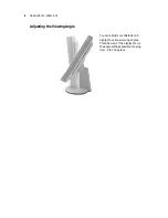
Page 12: ...VSS15X VSS15X TR Adjusting the Viewing Angle You can adjust your VitalScreen S display to various viewing angles This side view of the display shows the angle settings possible ranging from 5 to 25 d...

Page 13: ...cting the AC Power You must use the Ault power adapter with this display unit 1 Plug the AC power cord into the power adapter 2 Plug the power connector into the locking mini DIN port on the back pane...

Page 14: ...wo units 2 Plug the video cable into the D sub VGA connector port on the back panel 3 Plug the other end of the video cable into the VGA port on the computer 4 Make sure the cables are properly aligne...

Page 15: ...volume of the stereo speakers by using the volume control function on the onscreen display menu Note In some instances the volume control function may be disabled If so the volume is set to the maxim...

Page 16: ...rd This standard provides four power saving modes based on the display detecting the horizontal or vertical sync signals The following table describes the four modes When the display is in power savin...

Page 17: ...the OSD menu by pressing the Function UP button when the display is powered up If your computer is in power saving mode or is powered down the OSD menu is inaccessible 1 2 3 4 1 Function UP and DOWN b...

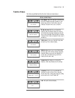
Page 18: ...us When a menu item is highlighted its submenu and a description of the submenu item appears below the main menu bar Auto Adjust Press the Function DOWN button to apply a display setting automatically...

Page 19: ...ttings is necessary if the results from the Auto Adjust function are not satisfactory OSD Control Allows you to adjust the position and setting of the onscreen display MISC Control Allows you to selec...

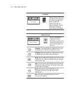
Page 20: ...button to move the display screen horizontally to the desired position V Position Press the Adjust PLUS or MINUS button to move the display screen vertically to the desired position Phase Press the Ad...

Page 21: ...rol icon selected press either Function Enter button to activate the submenu OSD H Position Press the Adjust PLUS or MINUS button to move the OSD menu horizontally OSD V Position Press the Adjust PLUS...

Page 22: ...e Adjust PLUS or MINUS button to select the desired OSD display language Languages supported English German French Spanish and Italian Audio Volume Press the Adjust PLUS or MINUS button to decrease or...

Page 23: ...ss the Adjust PLUS or MINUS button to select the display color The available options are 9300 6500 and User The 9300 and 6500 options allow you to set the Color Temperature to CIE coordinate value 930...

Page 24: ...400 With the Graph Text icon selected press the Adjust PLUS or MINUS button to change the resolution from one setting to the other Exit Allows you to exit the OSD menu With the Exit icon selected pre...

Page 25: ...me ms Rise Fall 20 5 ms typical Contrast ratio 500 1 typical 300 1 minimum Brightness non touch 300 cd m2 typical 230 cd m2 minimum Viewing angle degrees 70 70 L R horizontal 55 65 U D vertical Pixel...

Page 26: ...18 70 09 31 47 7 VGA 640x400 25 18 70 09 31 47 8 VGA 640x480 25 18 59 94 31 47 9 VESA 640x480 31 50 72 81 37 86 10 VESA 640x480 31 50 75 00 37 50 11 VESA 800x600 36 00 56 25 35 16 12 SVGA 800x600 40 0...

Page 27: ...Hz The screen display may not be centered and this warning message appears Incoming resolution The incoming resolution is higher than 1024 x 768 The video data turns off and this warning message appe...

Page 28: ...roblem Display indicates No Signal When there is no video input signal from the source video port the OSD shows this message Solution Check that the video cable is connected securely to the computer a...

Page 29: ...6 F front panel 2 Function buttons 2 G Graph Text menu 11 16 Graphic Control menu 11 15 I identifying components 2 information ordering parts 26 product vi technical 17 installing display 5 L LCD scre...

Page 30: ...formation 17 timing supported 18 touch screen cleaning vii connecting 8 troubleshooting 19 U unpacking display 1 V VESA DPMS 8 VGA cable connecting 6 connector 3 viewing angle adjusting 4 W warranty 2...

Page 31: ...arranty period begins on the date of shipment from Planar The goods sold hereunder are warranted for a period of 36 months from date of shipment unless otherwise agreed to by Buyer and Planar No exten...

Page 32: ...WARRANTIES OF MERCHANTABILITY OR FITNESS FOR A PARTICULAR PURPOSE ITS RESPONSIBILITY TO REPAIR OR REPLACE DEFECTIVE PRODUCTS IS THE SOLE AND EXCLUSIVE REMEDY PROVIDED TO THE BUYER FOR BREACH OF THIS...

Page 33: ...or fax your request to 503 748 1493 You need the unit s serial number and a brief description of the problem to receive an RMA number In Europe call Planar Customer Service at 358 9 420 01 between 8 A...

Page 34: ...Certified Display with desk stand and European power cord 997 2262 01 VSS 15X 15 inch XGA VitalScreen S Medically Certified Display with mounting plate and US power cord 997 2265 01 VSS 15X 15 inch XG...

Page 35: ...desk stand and European power cord 997 2402 01 VSS 15X TR 15 inch XGA VitalScreen S Medically Certified Display with mounting plate and US power cord 997 2403 01 VSS 15X TR 15 inch XGA VitalScreen S...

Page 36: ...93 fax sales planar com Medical Sales Planar Systems Inc 400 Fifth Avenue Waltham MA 02451 8738 USA 781 895 1155 phone 781 895 1133 fax medicalsales planar com Europe Asia Pacific Sales Planar Systems...

Reviews: