background image

User’s Guide | 17 

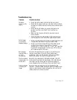
Troubleshooting 

Problem Possible 

Solution


No image 
appears on the 
screen. 


Check that all the power cord connections are secure. 


Check that the power buttons on the side and front of both 
monitors are switched on and that the power indicator light 
is green. 


Check that the DVI cables are securely fastened to the 
graphics card, the mirror-flip PCI card, and the two 
monitors. 


Make sure that the pins of the DVI connectors are not  
bent or broken. 


If only the bottom monitor appears to be working, make 
sure the graphics card is not in the single-monitor mode.   

Partial image  
or incorrectly 
displayed image. 


Check to see if the resolution of the computer/graphics card 
is higher than that of the LCD panels (1680 x 1050). 


Check to see that the output timing of the video signals  
is within the synchronous range of the LCD panels 
(horizontal: 30 – 94 kHz; vertical: 56 – 75 Hz).  The “Input Not 
Supported” message appears on the screen if the timing is 
not supported by the LCD panel. 

Both displays 
work but there is 
no stereo 
functionality. 

Be certain the graphics card is properly set up for the dual-
monitor stereo mode.  If you are using a professional 
application, make sure that OpenGL settings are enabled.  
Refer to the owner’s manual for the graphics card.   

The stereoscopic 
image appears to 
be inverted. 

Be certain the video cable to the bottom display is the left 
channel and the cable to the top display is the right channel.  
Also make sure that the image sent to the top monitor is 
mirror-flipped either by software or the mirror-flip PCI card.   

Only one display 
is showing an 
image. 

Be certain that your graphics card is configured for two 
monitors.  Use clone mode, horizontal span (also called stretch 
mode), or dual-monitor mode configuration.  Be sure that all 
video cables are securely connected. 

Summary of Contents for SD2220W

Page 1: ...SD2220W Stereoscopic Monitor USER S GUIDE www planar3d com...

Page 2: ...1992 www planar com 2009 Planar Systems Inc Planar is a registered trademark of Planar Systems Inc Other brands and names are the property of their respective owners Technical information in this docu...

Page 3: ...the half mirror Use a soft cloth moistened with water and or mild detergent to clean the display housing and stand Use only high quality and safety approved AC DC power adapters Disconnect the power...

Page 4: ...ox contains the following components Bottom monitor assembly with mirror support arms and mirror adjustment screws Bottom cable management cover Top monitor assembly Top cable management cover Beamspl...

Page 5: ...ft Two Analog VGA cables 6 ft and 10 ft Mirror flip PCI card Short DVI cables 14 in Product user s guide Captain style glasses 2 ea Spring clip style glasses 1 ea Terminator style glasses 2 ea Soft dr...

Page 6: ...he cables 7 Connect the power cords 8 Check the alignment 8 Product Use 9 Operating in 2D mode 9 User controls 10 OSD menu 11 Power management 13 Monitor Specifications 13 LCD Panel 13 Plug and Play 1...

Page 7: ...eates an unprecedented level of stereo 3D viewing quality and viewer comfort The StereoMirror monitor Stereo viewing is useful for the following applications Photogrammetry and remote sensing Geospati...

Page 8: ...ion Liquid crystal displays operate based on the ability of liquid crystal material to modulate plane polarized light The two AMLCDs in the SD2220W model have been manufactured so that the polarized l...

Page 9: ...proper stereo effect Once the two view points have been defined the 3D scene is rendered identically for each of the two view points Many commercial 3D applications already have stereo viewing modes u...

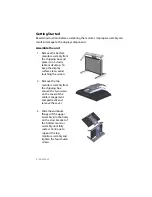
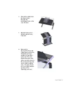
Page 10: ...y table or desktop To keep the display surface clean avoid touching the screen 2 Remove the top monitor assembly from the shipping box Loosen the two screws on the cover of the cable management compar...

Page 11: ...bottom cable covers if desired 6 Remove the beamsplitter from the shipping case With the StereoMirror logo oriented to the lower right insert the pins located on either side of the mirror frame into...

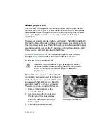
Page 12: ...he SD line Visit www planar3d com for more details on graphics cards software configuration and using side monitors with the SD2220W unit Install the mirror flip PCI card Proper ESD electrostatic disc...

Page 13: ...output of the dual channel graphics card Plug the other end into the input port labeled IN of the mirror flip PCI card 3 Plug one end of the 12 foot DVI cable into the output port of the mirror flip P...

Page 14: ...rms Rotating these screws raises or lowers the beamsplitter mirror Adjust the screws so that the corners of the reflected image of the upper monitor are aligned with the corners of the transmitted ima...

Page 15: ...o the locked upright position To move the mirror to the raised position use two hands to slide it up the mirror support arms and then raise it until it drops into the locked position To lower the mirr...

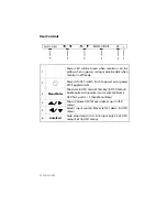
Page 16: ...ch Push to power on or power off Toggle switch 3 Menu Enter Shows main OSD menu Enter key in OSD menu Audio mute and unmute must activate Volume OSD first push then Menu Enter 4 Shows Volume OSD Moves...

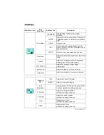
Page 17: ...rast Adjusts the contrast between the foreground and background of the screen image Auto Contrast Adjusts the contrast of screen image automatically Black Level Adjusts the black level of screen image...

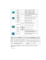
Page 18: ...1680 1400x1050 Selects the resolution of choice DDC CI ON OFF Turns ON OFF DDC CI support Recall Clear each old status and return all adjusted parameters to factory preset values Information Shows the...

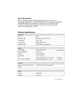
Page 19: ...light is amber Monitor Specifications LCD Panel Size 22W Display Type Active matrix color TFT LCD Resolution 1680 x 1050 Display Dot 1680 x RGB x 1050 Display Color 16 2M with FRC or Dithering Video I...

Page 20: ...k Disconnected 2 W maximum 240 VAC Meeting VESA DPM requirements measured from AC Input end of AC power cord Sync Input Analog Digital Signal Separate TTL compatible horizontal and vertical synchroniz...

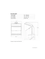
Page 21: ...User s Guide 15 Size and weight System width 23 1 588 mm System depth 20 7 525 mm System height 24 8 631 mm System weight 60 lb 27 kg Dimensions of monitor unit front and side...

Page 22: ...olvents for cleaning Software Compatibility OpenGL The SD2220W unit is compatible with OpenGL stereo An appropriate graphics card is required to drive the two monitors with DVI signals For professiona...

Page 23: ...he synchronous range of the LCD panels horizontal 30 94 kHz vertical 56 75 Hz The Input Not Supported message appears on the screen if the timing is not supported by the LCD panel Both displays work b...

Page 24: ...warranty includes a 1 year return to depot replacement warranty service Return the defective part of the system for a replacement with a comparable product All components have a 30 day inspection warr...

Page 25: ...be discarded with other refuse A number of recycling programs are available Do an online search of CRT Recycling for potential service providers in your area Important Recycle Instructions LCD lamps i...

Page 26: ......

Page 27: ...tation view answers to frequently asked questions FAQs and get troubleshooting advice Visit www planar3d com for specific questions about configuring the stereo monitor Customer First Technical Suppor...

Page 28: ...Planar Systems Inc 1195 NW Compton Drive Beaverton OR 97006 1992 Customer Service E mail planarsupport planar com Online www planar com support Voice 1 866 Planar1 1 866 752 6271...

Reviews: