background image

PY5500 User Manual (020-1103-00 Rev. A) 

26


Troubleshooting 

 
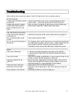
Before calling service personnel, please check the following chart for a possible solution:   
 
No image appears 
Is the power cord of the monitor 
connected? 

Check and see if the power cord is connected properly to the 
power outlet.    Is the main power switch in the “|” position? 

Is the power indicator amber? 

If yes, press the “on” button on the remote control or side panel. 

Is the S-video input and AV2 
input connected at the same 
time? 

If yes, remove either the S-Video input or AV2 input. 

 
The screen color is not normal 
Is the screen color unstable or 
monochrome? 

Check the connection of the source cable to ensure a proper fit.   

Do you see black dots on the 
screen? 

Clean surface with soft cloth.     

Do you see a partial blurring on 
the screen? 

This happens due to interference from surrounding magnetic fields, 
as created when speakers, steel structures, or high-voltage lines are 
placed near the monitor. Remove such materials from the 
immediate vicinity and use the OSD menu to adjust the screen. 

 
Others 
The screen is flickering 

1. Remove any highly magnetic material away from monitor.   
2. Adjust graphic interface (PC Mode) within allotted frequency 
parameters. 

The picture is dark 

Adjust the backlight and brightness. It takes several seconds for the 
monitor to warm up after the power is turned on.   

The picture appears to be 
ghosting 

Ensure the source equipment connection cables are less than 15 
meters (50ft.) If additional length is required, please contact your 
authorized dealer for a signal amplifier. (not provided) 

The picture size is incorrect 

Adjust picture format to desired image size. 

White does not look white 

Adjust the color temperature or alter “User” settings to preferred 
settings. 

Screen image is not centered 

Adjust picture format to desired image size.     


Summary of Contents for PY5500

Page 1: ...PY5500 USER MANUAL www planar com...

Page 2: ...use undesired operation Federal communications commission FCC statement This equipment has been tested and found to comply with the limits for a Class A digital device pursuant to part 15 of the FCC R...

Page 3: ...ns Disposal Do not use household or municipal waste collection services for disposal of electrica and electronic equipment EU countries require the use of separate recycling collection services Regist...

Page 4: ...he Power Cord 9 Connecting Using HDMI Cable BEST 9 Connecting to a Computer 9 Basic operation 10 Information 10 A Connecting the Power Cable 10 B Turning Power On 10 C Selecting Input Source 10 D Turn...

Page 5: ...e operation of the monitor and to protect it from overheating be sure these openings are not blocked or covered Do not place the monitor in a bookcase or cabinet unless proper ventilation is provided...

Page 6: ...the product in environments with heavy dust or high humidity may cause fire or electric shock Follow instructions for moving the product Ensure that the power connector and any other cables are unplug...

Page 7: ...Max resolution 1920 x 1080 Full HD format Ultra wide viewing angle 176 H 176 V Support PIP function OSD in 2 languages 1HDMI inputs with HDCP key protection Package Contents Open the package and ensur...

Page 8: ...PY5500 User Manual 020 1103 00 Rev A 7 Front Panel Control Panel LED Light and Front IR Sensor...

Page 9: ...tch AC socket 90 degree rotation Power Cord AC Power cord The power cord is used to power the LCD monitor from a standard wall outlet Connect the power cord into main power of the monitor where is pow...

Page 10: ...PY5500 is packed inside a boxed carton In order to protect the monitor during transportation additional packing material has been placed within the carton Before unpacking your monitor prepare a stab...

Page 11: ...to power off the monitor B Turning Power On Once power switch is on see above press the Power ON button on the side of the monitor or remote control C Selecting Input Source To select the Input Sourc...

Page 12: ...PY5500 User Manual 020 1103 00 Rev A 11 Remote control A Remote Control B Key Pad It is OK if all buttons are not functional...

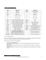
Page 13: ...ITEM FUNCTION On Monitor on MENU To enter OSD menu OFF Monitor off Menu Up MUTE Audio mute Menu Down INFO To indicate the status Menu Left PC For VGA choice Menu Right Video 1 To choose Component sour...

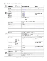
Page 14: ...n Off Off Select Source VGA HDMI1 HDMI 2 4 disable PIP PIP Mode Off Large PIP Middle PIP Small PIP Side by Side Off PIP Position Bottom Right Top Left Top Right Bottom Left Bottom Right Active when PI...

Page 15: ...deo Mode Front LED On Off On IRFM OFF 1 Hour 2 Hours 4 Hours Instant Off Avoid Image retention to slight frame motion Baud Rate 115200 38400 19200 9600 19200 Change Uarto Planar gPrboe gProbe is locke...

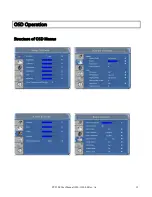
Page 16: ...PY5500 User Manual 020 1103 00 Rev A 15 OSD Operation Structure of OSD Menus...

Page 17: ...PY5500 User Manual 020 1103 00 Rev A 16...

Page 18: ...osition V Position Screen Scaling VGA SVGA XGA WXGA HDTV Full Screen Display Power Management VESA DPMS DVI DMPM OSD Language English Power source Power Input AC100 240V V Minimum Maximum 90 264V refe...

Page 19: ...OSD key 7 keys with lockout Key Wall mount VESA standard 400 x 200 400 x 600 with M8 screw hole mm RS232 2 way control communication firmware upgrade IR Arrive Distance Angle horizontal vertical Dista...

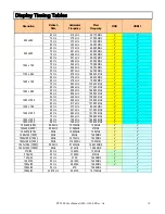
Page 20: ...Hz 85 9 kHz 148 500 MHz V V 1280 x 1024 60 Hz 64 0 kHz 108 000 MHz V V 75 Hz 80 0 kHz 135 000 MHz V V 85 Hz 91 1 kHz 157 500 MHz V V 1360 x 768 60 Hz 47 7 kHz 85 500 MHz V V 1400 x 1050 60 Hz 64 7 kHz...

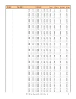
Page 21: ...6388 0 70 all 70 4 4 70 pwc op 1 16388 0 71 all 71 5 5 71 pwc op 1 16388 0 72 all 72 6 6 72 pwc op 1 16388 0 73 all 73 7 7 73 pwc op 1 16388 0 74 all 74 7 7 74 pwc op 1 16388 0 75 all 75 8 8 75 pwc op...

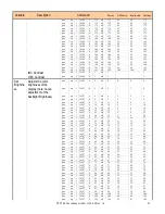
Page 22: ...all 134 54 54 134 pwc op 1 16388 0 135 all 135 55 55 135 pwc op 1 16388 0 136 all 136 56 56 136 pwc op 1 16388 0 137 all 137 57 57 137 pwc op 1 16388 0 138 all 138 57 57 138 pwc op 1 16388 0 139 all...

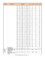
Page 23: ...16387 0 9 all 9 3 3 9 pwc op 1 16387 0 11 all 11 4 4 11 pwc op 1 16387 0 14 all 14 5 5 14 pwc op 1 16387 0 16 all 16 6 6 16 pwc op 1 16387 0 19 all 19 7 7 19 pwc op 1 16387 0 22 all 22 8 8 22 pwc op 1...

Page 24: ...387 0 182 all 182 71 71 182 pwc op 1 16387 0 184 all 184 72 72 184 pwc op 1 16387 0 187 all 187 73 73 187 pwc op 1 16387 0 190 all 190 74 74 190 pwc op 1 16387 0 193 all 193 75 75 193 pwc op 1 16387 0...

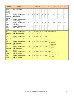
Page 25: ...DPMS mode Display changes to the desired DPMS mode setting pwc op 1 5126 0 0 all 0 Off Off 0 pwc op 1 5126 0 1 all 1 On On 1 Restore Default Setting Display restores all adjustable parameters back to...

Page 26: ...SD lock setting pwc op 2 13320 0 0 all 0 On On 0 Set BackLig h Display sends the current OSD BackLigh setting pwc o p 1 1638 9 0 Val all Value range 0 100 Get BackLig h Display sends the current OSD B...

Page 27: ...o interference from surrounding magnetic fields as created when speakers steel structures or high voltage lines are placed near the monitor Remove such materials from the immediate vicinity and use th...

Page 28: ...and C1 on Low Voltage Equipment Safety EN60950 2001 Safety of IT Equipment The Technical Construction File required by this Directive is maintained at the corporate headquarters of Planar Systems Inc...

Page 29: ...mail PlanarSupport planar com Online Technical Library http www planar com support Hours M F 3am 7pm ET 11am 3am GMT 2008 Planar Systems Inc Planar is a registered trademark of Planar System Inc Other...

Reviews: