background image

Safety Warnings and Precautions

1

Safety Warnings and Precautions

• THE MAINS PLUG OF THE POWER SUPPLY CORD SHALL REMAIN READILY OPERABLE. THE 

AC RECEPTACLE (MAINS SOCKET OUTLET) SHALL BE INSTALLED NEAR THE EQUIPMENT 
AND SHALL BE EASILY ACCESSIBLE. TO COMPLETELY DISCONNECT THIS EQUIPMENT FROM 
THE AC MAINS, DISCONNECT THE POWER CORD PLUG FROM THE AC RECEPTACLE.

• Do not place this display on an uneven, sloping or unstable surface (such as a trolley) 

where it may fall and cause damage to itself or others.

• Do not place this display near water, like a spa or pool, or in a position which will allow the 

splashing or spraying of water onto the display, like in front of an open window where rain 
water may enter.

• Do not install this display in a confined space without proper ventilation and air circulation, 

such as in a closed cabinet. Allow proper space around the display for dissipating heat 
inside. Do not block any openings and vents on the display. Overheating may result in 
hazards and electric shock.

• Installation of this display should only be performed by a qualified technician. Failure to 

install this display properly may cause injuries and damages to the personnels and the 
display itself. Check the installation regularly and maintain the display periodically to 
ensure the best working condition.

• Use only the accessories approved or recommended by the manufacturer to mount this 

display. Using wrong or unsuitable accessories may cause the display to fall and result in 
serious personal injuries. Make sure that the surface and fixing points are strong enough to 
sustain the weight of the display.

• To reduce the risk of electric shock, do not remove covers. No user serviceable parts inside. 

Refer servicing to qualified service personnel.

Important Safety Instructions

1. Read these instructions.
2. Keep these instructions.
3. Heed all warnings.
4. Follow all instructions.
5. Do not use this apparatus near water.
6. Clean only with dry cloth.

THIS EQUIPMENT MUST BE GROUNDED
To ensure safe operation, the three-pin 
plug must be inserted only into a 
standard three-pin power outlet which 
is effectively grounded through normal 
household wiring. Extension cords used 
with the equipment must have three 
cores and be correctly wired to provide 
connection to the ground. Wrongly 
wired extension cords are a major cause 
of fatalities.
The fact that the equipment operates 
satisfactorily does not imply that the 
power outlet is grounded or that the 
installation is completely safe. For your 
safety, if you are in any doubt about the 
effective grounding of the power outlet, 
please consult a qualified electrician.

The lightning flash with arrowhead 
symbol, within an equilateral triangle, is 
intended to alert the user to the presence 
of uninsulated "dangerous voltage" within 
the product's enclosure that may be of 
sufficient magnitude to constitute a risk of 
electric shock to persons.

The exclamation point within an 
equilateral triangle is intended to alert the 
user to the presence of important 
operating and maintenance (servicing) 
instructions in the literature 
accompanying the appliance.

Summary of Contents for PY4200

Page 1: ...PY4200 USER S GUIDE www planar com...

Page 2: ...rol DATE DESCRIPTION December 2010 Document number 020 1097 00 Rev A The information contained in this document is subject to change without notice This document contains proprietary information that...

Page 3: ...tice 9 Setting Up the Display 10 Mounting the Display 10 Installing the Display on a Wall 10 Installing the Optional Desktop Stands 11 Connecting Audio Video Signals 13 Connecting the VGA Input 13 Con...

Page 4: ...e Contrast 23 Adjusting the Brightness 23 Sound Menu 24 Option Menu 25 Setting Menu 27 Product Information 29 Specifications 29 Supported Input Signal Resolution 30 Supported PIP Input Signal Combinat...

Page 5: ...se the display to fall and result in serious personal injuries Make sure that the surface and fixing points are strong enough to sustain the weight of the display To reduce the risk of electric shock...

Page 6: ...eration is subject to the following two conditions 1 this device may not cause harmful interference and 2 this device must accept any interference received including interference that may cause undesi...

Page 7: ...99 9 of these pixels work normally 0 01 of the pixels may remain constantly lit in red blue or green or unlit This is a technical limitation of the LCD technology and is not a defect LCD screens like...

Page 8: ...e cardboard carton can be recycled Consider storing the packaging if possible for future transport of the display Do not leave plastic bags within reach of young children or babies Optional Accessorie...

Page 9: ...er in the OSD menu Down Up button Scrolls through settings in the OSD menu Left Right Scrolls through settings in the OSD menu Power button Turns the power of the display on or off Power indicator Ind...

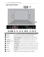
Page 10: ...to an external device SPEAKER OUT 8 12W x 2 Relays audio signals from the LINE IN AUDIO L R or HDMI jacks to external speakers AUDIO L R For connecting to the audio output of an external device such...

Page 11: ...tput of an external device such as a DVD player HDTV device or Laser disc player S VIDEO IN For connecting to the S video output of an external device such as a VCR or DVD player AV1 IN For connecting...

Page 12: ...VGA input directly DVI Press this button to select the DVI input directly Power Press this button to turn the power of the display on or off EXIT In the OSD menu press this button to return to the pre...

Page 13: ...2 Insert the supplied batteries ensuring that the positive and negative marked battery terminals match the and marks in the battery compartment Note The supplied batteries are provided for your conve...

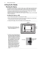
Page 14: ...ry and lint free cloth on a flat horizontal and object free surface Make sure that the size of the cloth is larger than the display 3 Gently lay the display on the cloth with the LCD screen facing dow...

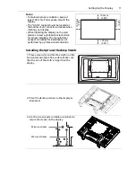
Page 15: ...installing The manufacturer accepts no liability for installations not performed by a professional technician Installing the Optional Desktop Stands 1 Place a clean dry and lint free cloth on a flat h...

Page 16: ...ed on desktop stands tie the display to the wall using commercially available screws eye bolts clamps and a sturdy rope as shown below Screw Holes Screw hook etc Commercially available Rope etc Commer...

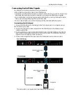
Page 17: ...inserted and firmly seated Connecting the VGA Input 1 Connect the VGA IN jack on the display to the VGA output jack on a computer using a Mini D Sub 15 pin cable 2 Connect the computer s audio output...

Page 18: ...ly connect the computer s HDMI output jack to the HDMI input jack on the display 2 Connect the computer s audio output jack to the LINE IN jack on the display using a suitable audio cable 3 To view vi...

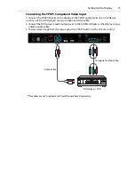
Page 19: ...as a VCR or DVD player using a component video cable 2 Connect the DVD player s audio output jacks to the AUDIO L R jacks on the display using a suitable audio cable 3 To view video image from this in...

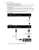
Page 20: ...f a second display is used connect the AV1 OUT jack on the first display to the AV1 IN jack on the second display using an AV cable This relays the input signal from the first display to the second on...

Page 21: ...with a built in 12W 12W amplifier so you can connect external speakers to the display directly Connect the external speakers to the SPEAKER OUT jacks on the display Note The volume of the external spe...

Page 22: ...d or frayed or change the plug type on the power cord Be aware of the total loading when using extension cords or multiple outlet power boards This display has no power switch When installing the disp...

Page 23: ...e remote control to switch to the corresponding inputs directly You can also use the INPUT button on the control panel to select an input signal Adjusting Audio Volume Level Press the Up button on the...

Page 24: ...Contrast Brightness Color Tint Sharpness Backlight DCR Color Temp Input Resolution 22 Sound Volume Mute Audio Source Speaker 24 Option Aspect ratio PIP Video Source Auto Adjustment Clock Frequency Pha...

Page 25: ...on to select an item 3 Press the INPUT button to confirm selections 3 Press the ENTER button to confirm selections 4 Press Up or Down to select a feature and press Left or Right to adjust settings Pre...

Page 26: ...below 50 to 100 Tint Adjusts the User Color mode 50 to 100 Sharpness Adjusts the sharpness of the image when the Picture Mode is set to User 0 to 10 Backlight Adjusts the backlight intensity of the L...

Page 27: ...t level 2 Gradually decrease the contrast level until you reach the point where the details in the bright areas of the image can be seen clearly Do not further decrease the contrast level to avoid los...

Page 28: ...or off the mute function ON OFF Audio Source Selects the audio input source Audio 1 Audio 2 Line in HDMI Speaker Selects the audio output source Note This is an optional feature and may not be availab...

Page 29: ...for more information on all supported signal source types In PIP mode only the audio from the Main Input picture will be available Video Source Selects a video input source AV S Video VGA YPbPr DVI H...

Page 30: ...sensor function When turned on the sensor adjusts ambient light sensitivity of the display OFF HIGH LOW Blue Screen Turns on or off the blue screen function When turned on the display will show a blue...

Page 31: ...es priority over other schedules that are set up to operate weekly When schedule items overlap scheduled power on time has priority over scheduled power off time If there are two schedule items progra...

Page 32: ...r off the auto adjustment function When turned on the display will automatically optimize image display Note This feature is only available for the VGA input ON OFF DDC CI Turns on or off the Display...

Page 33: ...in Output Computer VGA Mini D Sub 15 pin Video Composite Video BNC jacks Speaker External speaker jack 12W 12W 8 Ohms Audio L R RCA jacks Control RS 232C Mini D Sub 9 pin Power supply 100 240V AC 50 6...

Page 34: ...VI 640 x 480 60Hz 640 x 480 72Hz 640 x 480 75Hz 720 x 400 70Hz 800 x 600 60Hz 800 x 600 75Hz 1024 x 768 60Hz 1024 x 768 75Hz 1280 x 768 60Hz 1280 x 960 60Hz 1280 x 1024 60Hz 1360 x 768 60Hz 1366 x 768...

Page 35: ...Product Information 31 Supported PIP Input Signal Combination Main picture signal source AV S Video VGA YPbPr DVI HDMI Sub picture signal source AV S Video VGA YPbPr DVI HDMI...

Page 36: ...600 60Hz 800 x 600 75Hz 1024 x 768 60Hz 1024 x 768 75Hz 1280 x 768 60Hz 1280 x 960 60Hz 1280 x 1024 60Hz 1360 x 768 60Hz 1366 x 768 60Hz 1600 x 1200 60Hz 1920 x 1080 60Hz 640 x 480 60Hz 640 x 480 72H...

Page 37: ...4 x 768 75Hz 1280 x 768 60Hz 1280 x 960 60Hz 1280 x 1024 60Hz 1360 x 768 60Hz 1366 x 768 60Hz 1600 x 1200 60Hz 1920 x 1080 60Hz 640 x 480 60Hz 640 x 480 72Hz 640 x 480 75Hz 720 x 400 70Hz 800 x 600 60...

Page 38: ...Hz 720 x 400 70Hz 800 x 600 60Hz 800 x 600 75Hz 1024 x 768 60Hz 1024 x 768 75Hz 1280 x 768 60Hz 1280 x 960 60Hz 1280 x 1024 60Hz 1360 x 768 60Hz 1366 x 768 60Hz 1600 x 1200 60Hz 1920 x 1080 60Hz 1080p...

Page 39: ...24 x 768 75Hz 1280 x 768 60Hz 1280 x 960 60Hz 1280 x 1024 60Hz 1360 x 768 60Hz 1366 x 768 60Hz 1600 x 1200 60Hz 1920 x 1080 60Hz 640 x 480 60Hz 640 x 480 72Hz 640 x 480 75Hz 720 x 400 70Hz 800 x 600 6...

Page 40: ...60Hz 1280 x 960 60Hz 1280 x 1024 60Hz 1360 x 768 60Hz 1366 x 768 60Hz 1600 x 1200 60Hz 1920 x 1080 60Hz 576i 50Hz 480i 60Hz 480p 60Hz 576p 50Hz 720p 50Hz 640 x 480 60Hz 640 x 480 72Hz 640 x 480 75Hz 7...

Page 41: ...0Hz 1080i 60Hz 1080p 50Hz 1080p 60Hz 640 x 480 60Hz 640 x 480 72Hz 640 x 480 75Hz 720 x 400 70Hz 800 x 600 60Hz 800 x 600 75Hz 1024 x 768 60Hz 1024 x 768 75Hz 1280 x 768 60Hz 1280 x 960 60Hz 1280 x 10...

Page 42: ...20p 50Hz 720p 60Hz 1080i 50Hz 1080i 60Hz 1080p 50Hz 1080p 60Hz 640 x 480 60Hz 640 x 480 72Hz 640 x 480 75Hz 720 x 400 70Hz 800 x 600 60Hz 800 x 600 75Hz 1024 x 768 60Hz 1024 x 768 75Hz 1280 x 768 60Hz...

Page 43: ...5Hz 720 x 400 70Hz 800 x 600 60Hz 800 x 600 75Hz 1024 x 768 60Hz 1024 x 768 75Hz 1280 x 768 60Hz 1280 x 960 60Hz 1280 x 1024 60Hz 1360 x 768 60Hz 1366 x 768 60Hz 1600 x 1200 60Hz 1920 x 1080 60Hz 1080...

Page 44: ...re HDMI Sub picture YPbPr 576i 50Hz 480i 60Hz 480p 60Hz 576p 50Hz 720p 50Hz 720p 60Hz 1080i 50Hz 1080i 60Hz 1080p 50Hz 1080p 60Hz 1080p 60Hz 1080p 50Hz 1080i 60Hz 1080i 50Hz 720p 60Hz 720p 50Hz 576p 5...

Page 45: ...terfaces you can connect multiple displays serially daisy chain to a computer for management You can connect up to 16 displays Note This function requires an RS 232C port equipped computer with the di...

Page 46: ...t Signal Resolution on page 30 to select a supported resolution and try again Use the Auto Adjustment function See Auto Adjustment on page 25 to let the display automatically optimize the display of c...

Page 47: ...h screen drivers warranty information and access to Planar s Technical Library for online troubleshooting To speak with Planar Customer Support please have your model and serial number available and d...

Page 48: ...8pm Eastern Time M F 5am 5pm Pacific Time Europe and Asia Pacific Support Tel 358 9 420 01 Hours M F 7 00am 4pm CET 2010 Planar Systems Inc 05 08 Planar is a registered trademark of Planar Systems In...

Reviews: