background image


CONNECTO

R PI

N


ASS

IG

N

M

ENT


1

5

6

10

11

15


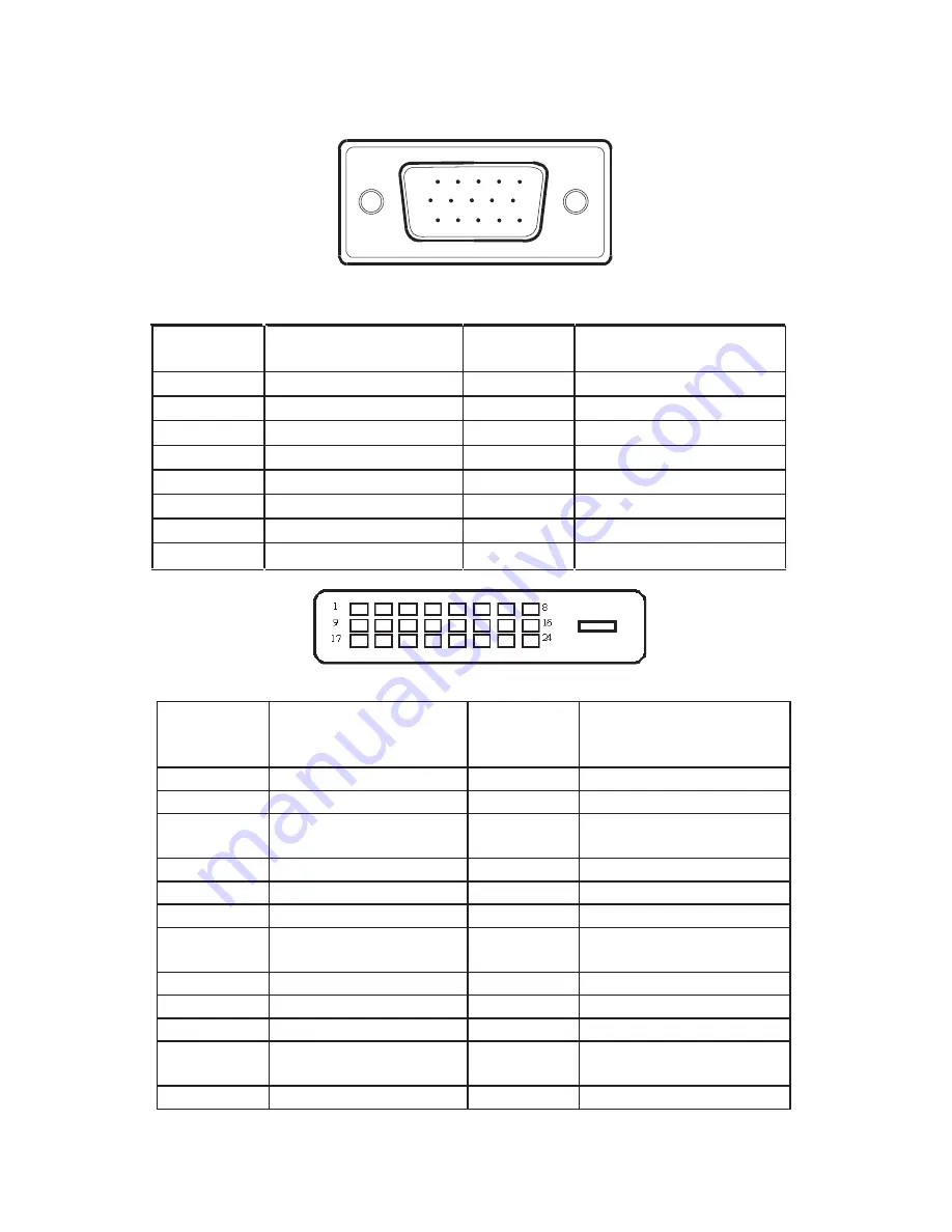
15 - Pin Color Display Signal Cable 


PI

N


NO

. D

ESC

RIP

T

I

ON

 PI

N


NO

. D

ESC

RIP

T

I

ON


1. 

Red 

  9. 

+5V 

2. Green 

10. 

Detect 

Cable 

3. Blue 

11. 

Ground 

4. Ground 

12. 

DDC-Serial 

Data 

5. Ground 

13. 

H-Sync 

6. R-Ground 

14. 

V-Sync 

7. G-Ground 

15. 

DDC-Serial 

Clock 

8. B-Ground 


24 - Pin Color Display Signal Cable


PIN NO. 


DESCRIPTION PIN 

NO.  DESCRIPTION 

1. 

TMDS Data 2- 

13. 

TMDS Data 3+ 

2. 

TMDS Data 2+ 

14. 

+5V Power 

3. 

TMDS Data 2/4 

Shield 

15. 

Ground(for+5V) 

4. 

TMDS Data 4- 

16. 

Hot Plug Detect 

5. 

TMDS Data 4+ 

17. 

TMDS Data 0- 

6. 

DDC Clock 

18. 

TMDS Data 0+ 

7. 

DDC Data 

19. 

TMDS Data 0/5 

Shield 

8. 

N.C. 

20. 

TMDS Data 5- 

  9. 

TMDS Data 1- 

21. 

TMDS Data 5+ 

10. 

TMDS Data 1+ 

22. 

TMDS Clock Shield 

11. 

TMDS Data 1/3 

Shield 

23. 

TMDS Clock + 

12. 

TMDS Data 3- 

24. 

TMDS Clock - 

23

Summary of Contents for PX2210MV

Page 1: ......

Page 2: ...ts are reserved No part of this document may be reproduced translated to another language or stored in a retrieval system or transmitted by any means electronic mechanical photocopying recording or ot...

Page 3: ...ting the viewing angle 10 Operating instructions 11 General instructions 11 Front panel control 12 How to adjust a setting 13 Adjusting the picture 14 17 Plug and play 18 Technical support FAQ 19 Erro...

Page 4: ...and on the user is encouraged to try to correct the interference by one or more of the following measures 1 Reorient or relocate the receiving antenna 2 Increase the separation between the equipment a...

Page 5: ...g will fit only into a grounded power outlet as a safety feature If your outlet does not accommodate the three wire plug have an electrician install the correct outlet or use an adapter to ground the...

Page 6: ...of the LCD screen an afterimage of the previous screen may remain after switching the image when the same image has been displayed for a long time The monitor will slowly recover from this x When the...

Page 7: ...t face down prevent the monitor from being scratched Lay the Put a piece of soft cloth on the able beforehand to shock or damage Unplug the monitor before removal or installation to avoid electric Do...

Page 8: ...e AC power cord one end to LCD monitor s AC input socket the other end to Wall outlet Connecting the Audio Cable Connect the audio cable between the monitor s audio input and the PC s audio output Cau...

Page 9: ...x Hold the stand so you do not topple the monitor when you change the monitor s angle x You are able to adjust the monitor s angle from 5q to 19q Figure 3 NOTES x Do not touch the LCD screen when you...

Page 10: ...djusted to your personal preferences x The power cord should be connected x Connect the video cable from the monitor to the video card x Press the power button to turn on the monitor position The powe...

Page 11: ...button while the monitor is off and then press power button to turn the monitor on NOTES x Do not install the monitor in a location near heat sources such as radiators or air ducts or in a place subj...

Page 12: ...ton to activate it If the function selected has a sub menu press or again to navigate through the sub menu functions Once the desired function is highlighted press MENU button to activate it 3 Press o...

Page 13: ...m Main Menu Icon Sub Menu Description Enhances Contrast Ratio Note When this function is turned On you cannot adjust the current settings for Contrast Brightness ECO mode or Gamma VGA input only VGA i...

Page 14: ...Main Menu Item Main Menu Icon Sub Menu Description 15...

Page 15: ...Main Menu Item Main Menu Icon Sub Menu Description 16...

Page 16: ...17 Main Menu Item Main Menu Icon Sub Menu Description...

Page 17: ...ST BE A VIDEO INPUT SIGNAL This monitor meets the Green monitor standards as set by the Video Electronics Standards Association VESA and The Swedish Confederation Employees NUTEK This feature is desig...

Page 18: ...onal by hitting the CAPS LOCK key on the keyboard while observing the CAPS LOCK LED The LED should either turn ON or OFF after hitting the CAPS LOCK key Missing one of the primary colors RED GREEN or...

Page 19: ...is properly connected If the connector is loose tighten the connector s screws 2 Check the signal cable s connection pins for damage INPUT NOT SUPPORT Your computer has been set to unsuitable display...

Page 20: ...60Hz Plug Play VESA DDC2B TM Power Consumption ON Mode 43W TYP OFF Mode 1W Input Connector D Sub mini 15 pin DVI D 24 pin HDMI Input Video Signal Analog 0 7Vp p Standard 75 Positive Digital DVI Digita...

Page 21: ...48 077 72 188 SVGA 800 x 600 46 875 75 Mac SVGA 832 x 624 49 726 74 551 1024 x 768 48 363 60 004 1024 x 768 56 476 70 069 1024 x 768 57 5 72 074 XGA 1024 x 768 60 023 75 029 1280 x 1024 67 981 60 02...

Page 22: ...ck 8 B Ground 24 Pin Color Display Signal Cable PIN NO DESCRIPTION PIN NO DESCRIPTION 1 TMDS Data 2 13 TMDS Data 3 2 TMDS Data 2 14 5V Power 3 TMDS Data 2 4 Shield 15 Ground for 5V 4 TMDS Data 4 16 Ho...

Page 23: ...DS Data 0 17 DDC CEC Ground 2 TMDS Data 2 Shield 10 TMDS Clock 18 5V Power 3 TMDS Data 2 11 TMDS Clock Shield 19 Hot Plug Detect 4 TMDS Data 1 12 TMDS Clock 5 TMDS Data 1Shield 13 CEC 6 TMDS Data 1 14...

Page 24: ...r touch screen or other Planar products visit our online store at www PlanarOnline com or find other stores who carry Planar products at http www planar com howtobuy Technical Support Visit Planar at...

Page 25: ...Q41G2201935 2B...

Reviews: