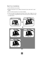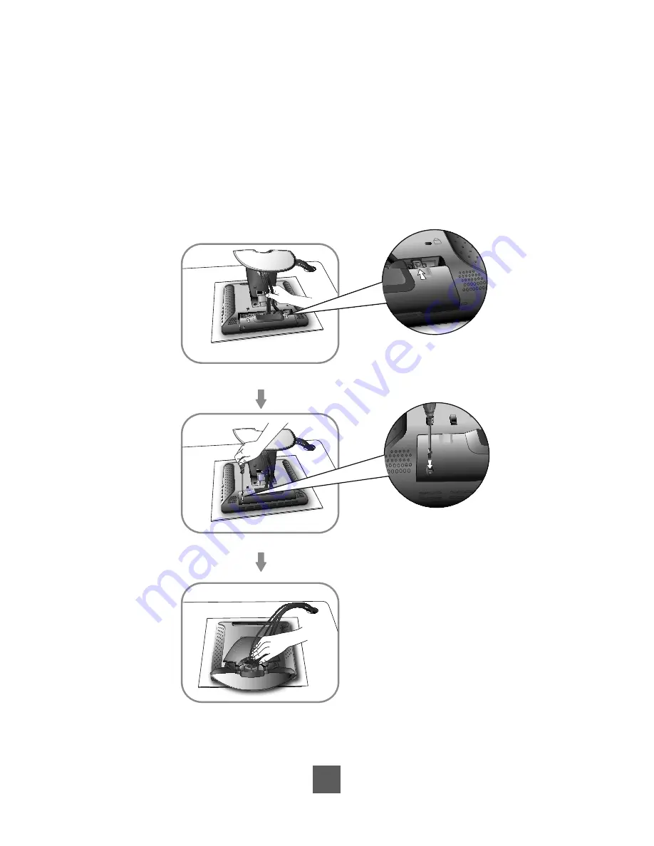
5. Take the optional cable cover and screw from the accessory box. Position all cables
under the cover lip as seen in the step 5 diagram.
6. Using a Philips Head screwdriver, insert the screw (CPMSP M3x10) into the cable cover
and monitor as seen in the step 6 diagram.
7. Re-attach the stand back cover to the LCD stand by pressing
fi
rmly until the tabs snap
into place as seen in the step 7 diagram. You may also keep the cables in order by using
the cable organizer.
7
Step 7
K
Step 5
Step 6
K
K
Summary of Contents for PT2275SW
Page 1: ...PT2275SW PT2285PW Touch Screen LCD Monitor USER S GUIDE www planartouch com ...
Page 12: ...9 Figure 9 1 PT2275SW PT2285PW ...
Page 15: ...12 Remove the Deskstand Remove 4 screws and then remove hinge ...
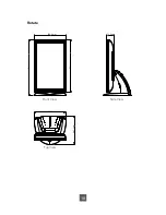
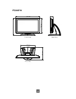
Page 22: ...Rotate 330 0 mm 73 2 mm 573 1 mm 538 5 mm 287 1 mm 327 7 mm Top View Front View Side View 19 ...
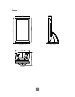
Page 24: ...Rotate 330 6 mm 71 9 mm 573 4 mm 539 2 mm 287 1 mm 327 7 mm Top View Front View Side View 21 ...
Page 28: ...25 ...


