background image


20

APPENDIX (cont.)


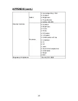
Switch 

  Auto Adjust Key / Exit 

 Contrast 

 Brightness 

 Power Button 

  MENU / ENTER 

External Controls: 

Functions 

 Contrast 

 Brightness 

 Focus 

 Clock 

 H.Position 

 V.Position 

  OSD location & Time 

 Language 

 C1 

 C2 

 sRBG


  User Color temperature 

 Information 

 Reset 

 Exit 

Regulatory Compliance  

                            UL,cUL,FCC-B,CE


Summary of Contents for PL1500

Page 1: ...PL1500...

Page 2: ...documentation view answers to frequently asked questions FAQs and get troubleshooting advice or email Planar your support question Talk to a Customer Service Representative To contact Planar s Custome...

Page 3: ...ghts are reserved No part of this document may be reproduced translated to another language or stored in a retrieval system or transmitted by any means electronic mechanical photocopying recording or...

Page 4: ...ge 6 Installation Instructions Installing the base 7 Power source 7 Cable connection 8 Adjusting the viewing angle 9 Operating Instructions General Instructions 10 How to adjust a setting 13 Adjusting...

Page 5: ...between the equipment and receiver 3 Connect the equipment into an outlet on a circuit different from that to which the receiver is connected 4 Consult the dealer or an experienced radio TV technicia...

Page 6: ...ess proper ventilation is provided z The monitor should be operated only from the type of power source indicated on the label If you are not sure of the type of power supplied to your home consult you...

Page 7: ...ttern you use The LCD screen has effective pixels of 99 99 or more It may include blemishes of 0 01 or less such as a missing pixel or a pixel lit all of the time Due to the nature of the LCD screen a...

Page 8: ...le Register Your Planar Products Today Thank you for choosing Planar To assure you receive all the benefits of your Planar product and services register your Planar product today Visit our website to...

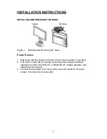
Page 9: ...ake sure that the power cord is the correct type required in your area 2 This LCD monitor has an Internal universal power supply that allows operation in either 100 120V AC or 220 240V AC voltage area...

Page 10: ...end to LCD monitor s VGA input socket the other end to the computer s VGA port and tighten the two screws on the cable connector Connecting the Power Cord Plug the AC power cord one end to LCD monito...

Page 11: ...to your own preference Hold the stand so you do not topple the monitor when you change the monitor s angle You are able to adjust the monitor s angle from 5 to 20 Figure 3 NOTES Do not touch the LCD s...

Page 12: ...nging these settings the picture can be adjusted to your personal preferences The power cord should be connected Connect the Signal cable from the monitor to the VGA card Press the power button to tur...

Page 13: ...it OSD menu when in volume OSD status Contrast Adjust contrast or adjust function Brightness Adjust brightness or adjust function Auto Adjust button Exit 1 When OSD menu is in active status this butto...

Page 14: ...excessive dust or mechanical vibration or shock Save the original shipping box and packing materials as they will come in handy if you ever have to ship your monitor For maximum protection repackage...

Page 15: ...ress the MENU button to activate it If the function selected has a sub menu press or again to navigate through the sub menu functions Once the desired function is highlighted press MENU button to acti...

Page 16: ...ck Adjust picture Clock to reduce Vertical Line noise H Position Adjust the horizontal position of the picture Image Position V Position Adjust the verticalposition of the picture C1 N A Recall C1 fro...

Page 17: ...erticalposition of the OSD OSD Setup OSD Timeout Adjust the OSD timeout Language Language N A Set OSD language Information Information N A Show the resolution H V frequency and input port of current i...

Page 18: ...PUT SIGNAL This monitor meets the Green monitor standards as set by the Video Electronics Standards Association VESA and or the United States Environmental Protection Agency EPA and The Swedish Confed...

Page 19: ...Card should be snugly seated in its slot Make sure monitor s video cable is properly connected to the computer Inspect monitor s video cable and make sure none of the pins are bent Make sure computer...

Page 20: ...light picture For FOCUS and CLOCK adjustment use dot pattern or win 95 98 shut down mode pattern ERROR MESSAGE POSSIBLE SOLUTION CABLE NOT CONNECTED 1 Check that the signal cable is properly connected...

Page 21: ...5MHz typ Max Resolution 1024 x 768 Plug Play VESA DDC2BTM ON Mode 25W For 2 CCFL 30W For 4 CCFL EPA ENERGY STAR OFF Mode 2W Input Connector D Sub 15pin Input Video Signal Analog 0 7Vp p standard 75 OH...

Page 22: ...ontrast Brightness Power Button MENU ENTER External Controls Functions Contrast Brightness Focus Clock H Position V Position OSD location Time Language C1 C2 sRBG User Color temperature Information Re...

Page 23: ...Hz 720 x 400 31 47 70 0 640 480 31 47 60 0 640 480 35 00 66 6 640 480 37 50 75 0 VGA 640 480 37 861 72 8 800 600 35 156 56 3 800 600 37 879 60 0 800 600 48 077 72 2 800 600 46 875 75 0 832 x 624 49 7...

Page 24: ...T 1 5 6 10 11 15 15 Pin Color Display Signal Cable PIN NO DESCRIPTION PI N NO DESCRIPTION 1 Red 9 5V 2 Green 10 VGA CON 3 Blue 11 RDX 4 TDX 12 DDC Serial Data 5 Ground 13 H Sync 6 R Ground 14 V Sync 7...

Page 25: ...R 97006 1992 www planar com 2006 Planar Systems Inc Planar is a registered trademark of Planar Systems Inc Other brands and names are the property of their respective owners Technical information in t...

Reviews: