LC640.480.21-065 Operations Manual (OM610-00)
23
Automatic Dimming (Manual Offset)
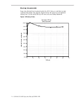
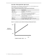
Lamp luminance varies depending on ambient light levels. An off-board light sensor is
used to determine the level. The user can adjust the luminance offset by varying the input
from 0 to 5 Vdc on pin 33 (DIM) of the video input connector (J1). See Figure 13 below.
Table 17. Automatic Dimming (Manual Offset) Specifications.
Description
Specification
DIM function
0 Vdc = max. negative offset (display always at min. luminance)
+2.5 Vdc = no offset
+5 Vdc = max. positive offset (display always at max. luminance)
DIM voltage to offset %
Linear relationship
SWI Setting
Switch 1 = OFF, Switch 2 = ON
Figure 13. Luminance Levels: Automatic Dimming (Manual Offset).
4200
0
600
Min.
Max.
1200
1800
2400
3000
3600
AMBIENT LIGHT LEVEL (lux)
DISPLAY
L
UMINANCE
D
IM
=
4.
5
Vd
c
D
IM
=
4.
0
Vd
c
D
IM
=
3.
5
Vd
c
D
IM
=
3.
0
Vd
c
D
IM
=
2.
5
Vd
c
D
IM
=
2.
0
Vd
c
D
IM
=
1.
5
Vd
c
D
IM
=
1.
0
Vd
c
D
IM
=
0.
5
Vd
c
Controlled Luminance Mode
This function compensates for the luminance degradation of the lamps over time and
constrains the maximum display luminance to approximately 700 cd/m
2
. Using a light
sensor that measures the lamp luminance inside the light box, the microcontroller adjusts
the lamp current to maintain constant luminance at the desired luminance level. For
example, if DIM = 2.5V (corresponding to a 50% luminance level) in analog dimming
mode, then the display luminance will be maintained at approximately 350 cd/m
2
. The
controlled luminance mode is enabled when pin 32 (/CBM) on J1 is low.


