LC640.480.21-065 Operations Manual (OM610-00)
18
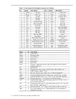
Table 11. Video Input and Backlight Connector (J1) Pinouts.
Pin
Signal
Description
Pin
Signal
Description
1
GND
Ground
2
CLK
Video clock
3
HSync
Horiz. sync
4
VSync
Vert. sync
5
GND
Ground
6
R0
Red data (LSB)
7
R1
Red data
8
R2
Red data
9
R3
Red data
10
R4
Red data
11
R5
Red data (MSB)
12
GND
Ground
13
G0
Green data (LSB)
14
G1
Green data
15
G2
Green data
16
G3
Green data
17
G4
Green data
18
G5
Green data (MSB)
19
GND
Ground
20
B0
Blue data (LSB)
21
B1
Blue data
22
B2
Blue data
23
B3
Blue data
24
B4
Blue data
25
B5
Blue data (MSB)
26
GND
Ground
27
DE
Data Enable
28
V
CC
AMLCD power
29
V
CC
AMLCD and fan power
30
GND
Ground
31
DPS
Display scan select
32
/CBM
Controlled luminance
33
DIM
Analog dimming control
34
DIMREF
Dim reference
35
INV
Inverter control
36
GND
Ground
37
ALS
Ambient light sensor
38
TS1
Temperature sensor
39
/HT
Heater indicator
40
/OHT
Overtemp indicator
Signal
I/O
Description
CLK
I
Video Clock
HSync
I
Horizontal Sync
Vsync
I
Vertical Sync
R0-R5
I
Red Data
G0-G5
I
Green Data
B0-B5
I
Blue Data
GND
I
Ground – Signal return for logic and power supplies. Isolated from the
display metal bezel.
DE
I
Data Enable
DPS
I
Display Scan - Low or open = normal; High = image upside down
V
CC
I
AMLCD power supply: +5 Vdc
INV
I
Inverter - High or open = enable; Low = disable (backlight off)
/CBM
I
Controlled Luminance Mode - High or open = normal; Low = enabled
DIM
I
Analog Dimming Control - 0 to +5 Vdc; +5 Vdc is maximum luminance
DIMREF
O
Dimming Reference - +5 Vdc reference for analog dimming
ALS
O
Ambient Light Sensor - signal to microprocessor: 0 to +5 Vdc; +5 Vdc is
lowest ambient light level
TSI
O
Temperature Sensor (no. 1) - signal to microprocessor: 0 to +5 Vdc, with
0C = 0.5 Vdc,
and 10 mv/
°
C
/HT
O
Heating Indicator - Low = display is heating and backlight is turned off
/OHT
O
Over-temp Indicator - Low = display temperature is at maximum and
luminance is reduced

