


10
LC1502R User’s Guide
(020-0315-02B)
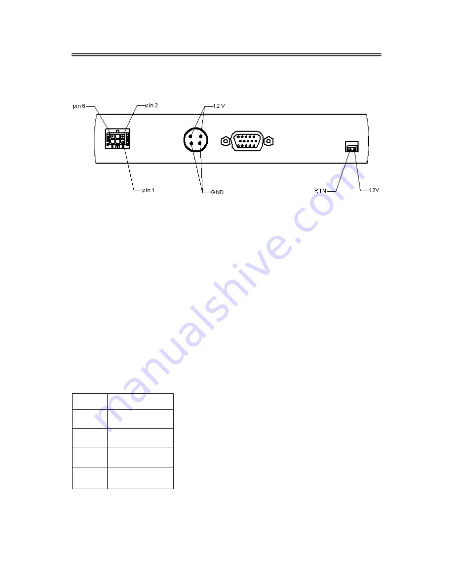
Connector View
Connector Descriptions
1. Video Interface Connector
Standard D-sub Analog; 15-pin D-sub connector
2. Power Input Connector
Connector type: 4-pin mini DIN socket
Manufacturer: Singatron Enterprise Co. (Taiwan)
Part Number: 2MJ-0402A120
Mating Connector: 2MP-0402 series
Power Connector Pin Configuration
Pin
Description
1
+12V DC
2
+12V DC
3
Ground
4
Ground
Summary of Contents for LC1502R SERIES
Page 1: ...LC1502R SERIES USER S GUIDE www planar com ...
Page 3: ...LC1502R User s Guide 020 0315 02B 3 ...
Page 4: ...4 LC1502R User s Guide 020 0315 02B ...
Page 8: ...8 LC1502R User s Guide 020 0315 02B Package Overview VGA Signal Cable Quick Start Guide ...
Page 9: ...LC1502R User s Guide 020 0315 02B 9 Installation Product Overview Front View Rear View ...


