EL512.256-H Series Operations Manual (020-0354-00A)
4
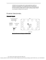
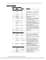
Input to the Display
Table1. Input to the Display.
Pins Signal
Symbol
Description
J1(Data/power input connector)
1, 2
Voltage
Vcc2
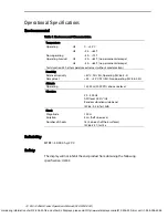
Supply voltage (+11…+30V) converted
to required internal high voltages (see
J2).
3, 4
Voltage
Vcc1
Supply voltage (+5 V) for the logic (see
J2).
5
Reserved
Reserved, do not connect.
6, 8, 10
Ground
GND
Signal return.
7
Two-bit data
TVID
Second data input for two bit parallel
mode. The TVID input is for odd
columns
and the VID for even ones.
9
Vertical Sync
VS
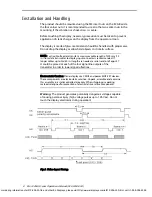
The vertical sync signal VS controls the
vertical position of the picture.
11 Horizontal
Sync
HS
The horizontal sync signal HS controls the
internal row counter and the
horizontal
position of the picture.
13
Video Clock
VCLK
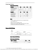
The VCLK signal shifts data present on
the VID and TVID lines into the display
system. VCLK is active on the rising edge.
15
Video Data
VID
Signal that supplies the pixel information
to the system.
12, 14,
16
Ground GND Signal
return.
J2 (Optional power input connector)
1
Voltage
Vcc2
Same as J1, Pins 1, 2 (not necessary to
connect if power is supplied via J1).
2, 3
Ground
GND
Same as J1 Pins 6, 8, 10, 12, 14, 16 (not
necessary to connect if power is
supplied
via J1).
4
Voltage
Vcc1
Same as J1 Pins 3, 4 (not necessary to
connect if power is supplied via J1).
5 Low
Power
_LOWPWR
The
power
consumption of the display is
lowered to LOWPWR values if
the
_LOWPWR is low, internally pulled high if
left disconnected.
6
Enable
ENABLE
The operation of the display unit is
disabled if the ENABLE input is low,
internally pulled high if left disconnected.
J3 (Optional control input connector)
1 Luminance
Pot.1
LUMPOT1
Input for external luminance control (see
page 8). Can be left disconnected.
2 Luminance
Pot.2
LUMPOT2
Input for external luminance control. Can
be left disconnected.
3, 4
Reserved
Reserved, do not connect.
For ordering information of el512-256-h3-frb and other EL Displays, please visit http://www.eldisplays.com/el512-256-h3-frb/ or call +1-888-394-4998.


