background image

Power Management Menu

The options in this menu provide control over the power management facilities. Only about half
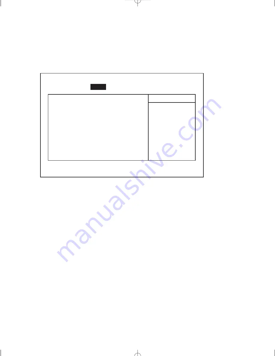
of the Power menu screen entries are actually visible at any one time; however, for illustrative pur-
poses, all of the Power menu entries are listed and annotated below.

System BIOS Power Management supported states are: Maximum Performance, Maximum
Battery Life, Customized, 
and Disabled. Wake-up event setup items are TBD.

Figure 21 — Power Management menu.

Power Savings

This option enables and selects the kind of power management, or it can be used to disable power
management. The options are: Maximum Performance, Maximum Battery Life, Customized, and
DisabledThe default is Customized.

Idle Mode

This option enables power saving during Idle Mode. Idle Mode slows down the CPU during brief
periods when the system is not busy. The default is Off.

Standby Timeout

This option enables and sets the duration of inactivity required before the system is placed in
Standby mode, or it disables Standby Timeout. The options are: Off, 1 min, 2 min, 4 min, 6 min,
8 min, 12 min, 
and 16 min. The default is Off.

Suspend Timeout

This option enables and sets the inactivity duration required to elapse before the system is placed
in Suspend mode from Standby mode, or it disables Suspend Timeout. The options are: Off, 5
min, 10 min, 20 min, 30  min, 40 min, 
and 60 min. The default is Off.

26

Planar Clean Screen II PC User’s Manual

Power Savings:

[Customized]

Idle Mode:

[Off]

Standby Timeout:

[Off]

Auto Suspend Timeout:

[Off]

Resume On Time:

[Off]

Resume Time:

[00.00.00]

Item Specific Help

Use < 

↑ 

> or < 

↓ 

> to select

a device, then press < + > to
move it down the list. Press
< esc> to exit this menu.

F1

Help

↑↓

Select Item

-/+ Change Values

F9

Set Defaults

ESC

Exit

↔ 

Select Menu

Enter Select 

©

Sub-Menu

F10 Save and Exit

PhoenixBIOS Setup Utility

Main

Advanced

Power

Boot

Exit

CS II Manual LAYOUT#2304   3/25/99  11:16 AM  Page 26

Summary of Contents for C3215 Clean Screen II

Page 1: ...Planar Clean Screen II PC User s Manual Model Number C3215...

Page 2: ...LANAR CLEAN SCREEN II PC Integrated Computer with LCD Color Display USER S MANUAL Model Number C3215 and Options Document Part Number C3DOC 2 Copyright 1999 Planar Display Solutions All rights reserve...

Page 3: ...Business Machines Corporation MS DOS is a registered trademark of Microsoft Corporation MMX is a trademark and Intel and Pentium are registered trademarks of Intel Corporation Accutouch is a trademark...

Page 4: ...t different from the circuit to which the receiver is connected Consult an experienced radio TV technician for help Canadian Emissions Requirements This digital apparatus does not exceed the Class A l...

Page 5: ...the environmental specifications of the goods d neglect misuse or abuse of the goods or e modification or integration with other goods not covered by Planar s warranty when such modification or integ...

Page 6: ...viii What s in the box viii What s in the IS Manager s Kit viii What s in this manual viii What if I m missing something viii Safety Instructions ix Chapter One The Installation Express 1 Chapter Two...

Page 7: ...USB Connection 14 External Speakers 14 Powering Up the Clean Screen II PC 15 Setup F2 15 Driver Overview 15 Brightness Control 15 Chapter Five BIOS Setup 16 Entering the BIOS Setup Program 16 Setup S...

Page 8: ...gned and Available IRQs 34 DMAs 34 I O Address List 35 Appendix C Troubleshooting 36 Anti Virus Alert 36 Troubleshooting Procedure 36 Boot Failures 37 Problems At Initial System Startup 38 Problems Af...

Page 9: ...ether the Clean Screen II shipping box and the IS Manager s Kit contain everything you need for installation and setup What s in this manual This manual is an advanced guide for installation and setup...

Page 10: ...d plug set power cord included with the unit 8 After the Clean Screen II has been installed secure all electrical cords out of the way to pre vent the unit from being pulled off the table or other acc...

Page 11: ...r Clean Screen II PC User s Manual Front Panel Figure 1 Connections Bottom Figure 2 Power on Light Hard Disk Power Switch Power Connector USB 1 AT Keyboard COM A USB 2 LAN Floppy Connector COM B PC Ca...

Page 12: ...rientation of the power connector before plugging it into the unit Always secure the connector in place before turning on the Clean Screen II 6 Turn on the unit 7 Press F2 immediately when prompted to...

Page 13: ...r The system includes a 15 inch AMLCD TFT display supporting resolutions of 640 x 480 800 x 600 and 1024 x 768 The entire unit is rated to with stand shocks of up to 50 g is powered by a single power...

Page 14: ...sing a floppy disk drive through a custom connector This is for diagnostic and service use only Front Panel Figure 4 Connections Bottom Figure 5 Chapter Two The Clean Screen II PC 3 Power on Light Har...

Page 15: ...in access to the unit Inside Figure 7 4 Planar Clean Screen II PC User s Manual Twelve T25 Torx screws Four holes for standard Planar mounting options 10 32 Three T20 Torx screws Touch Controller Boar...

Page 16: ...d disk memory or fuse The display unit contained beneath the motherboard uses high voltages The display unit is not field serviceable and its connections are easily damaged Static sensitive equipment...

Page 17: ...ct it from the power source 2 Use a static free workstation 3 Place Clean Screen II face down on a secure flat surface using a cloth or other non abrasive material to protect the display 4 Remove the...

Page 18: ...ve 2 Placing your hands on both sides of the T Bar gently insert the memory module into the empty socket Ensure correct orientation using the module notch located next to the contacts 3 Push the modul...

Page 19: ...IOS yes 816K to 896K 000CC000 000DFFFF ISA bus or UBE yes 896K to 1M 000E0000 000FFFFF Shadowed System ROM BIOS yes 1M to 16M 00100000 00FFFFFF DRAM yes If no DRAM ISA or PCI memory no 16M to 64M 0100...

Page 20: ...screws attach the hard disk to the hard disk cage 3 Gently plug the I O cable into the slotted I O jack on the hard disk 4 Gently plug the power cable into the hard disk power jack 5 Replace the back...

Page 21: ...y in compliance with local regulations 4 Upon startup the system defaults will load Enter Setup and go to the Exit menu to restore the CMOS settings saved in your flash memory See Chapter Five BIOS Se...

Page 22: ...A 5 A 1 Remove the back housing as above 2 Using a small jeweler type flat screwdriver gently pry up on the fuse 3 Snap in a new fuse that meets the above specifications Chapter Three Hardware Install...

Page 23: ...ec ommends a minimum of 1 rear clearance 3 Use only mounting hardware that complies with OSHA NFPA and local as well as country building codes 4 Ensure the weight or load limit of the mount is 3 times...

Page 24: ...Clean Screen II can use any AT style keyboard USB ports are also provided to support USB keyboards Connecting Peripherals Mouse The Clean Screen II PC uses a serial type mouse COM A is the default A U...

Page 25: ...you will be using AC power you will need to use the AC power supply adapter that was packed with your Clean Screen II If you will be using a Planar mounting stand with batteries you will use its powe...

Page 26: ...ered the Clean Screen II PC with an operating system pre loaded then the display network and touch drivers will already be loaded on the hard disk Otherwise you will need to check the floppy disks tha...

Page 27: ...keys are used to leave a menu and then return the active field is always at the beginning of the menu Fields with a triangle to the left are sub menu headings pressing enter when the cursor rests on o...

Page 28: ...sub menu There you can select Autotype Fixed Disk to allow the system to detect the drive type automatically The entry in the Main menu shows the drive selected Memory Cache Sub Menu The term memory c...

Page 29: ...iagnostic Screen This field specifies whether or not a boot time diagnostic screen of the BIOS boot progress is displayed during BIOS POST The options are Enabled and Disabled The default for this fie...

Page 30: ...t drive values for cylinders heads sectors track and write precompensation are entered For MultiBoot II the selections for this field are Auto ATAPI Removable IDE Removable CD ROM User and None The de...

Page 31: ...ed Transfer Mode This option selects the mode that the System BIOS uses to access the hard disk The selections are Standard Fast PIO 1 Fast PIO 2 Fast PIO 3 and Fast PIO 4 Older hard disks only suppor...

Page 32: ...sec The default is 30 sec Keyboard Auto Repeat Delay This option is used to set the delay between the time a key is pressed and the auto repeat feature begins Options are 1 4 sec 1 2 sec 3 4 sec and 1...

Page 33: ...D becomes corrupt ed The default is No This option is automatically reset to No after the ESCD is cleared Large Disk Access Mode If you are using a hard disk larger than 528 MB and are running MS DOS...

Page 34: ...he PCI configuration sub menu in order to configure the PCI devices PS2 Mouse You need to enable PS2 mouse to use USB mouse under Win 95 or NT 4 0 Legacy USB Support Again you need to enable to use US...

Page 35: ...tion is selected the OS configures the device When the Enabled option is selected the User configures the device The default is Auto Mode Sets the mode for Serial Port B The default is Normal Serial P...

Page 36: ...option are Auto OS Controlled Enabled or Disabled When the Auto option is selected the BIOS or the OS configures the device When the OS Controlled option is selected the OS configures the device When...

Page 37: ...s when the system is not busy The default is Off Standby Timeout This option enables and sets the duration of inactivity required before the system is placed in Standby mode or it disables Standby Tim...

Page 38: ...g is enabled This means access to the IDE drive will not allow the system to enter a power management state Access to the IDE will cause wake up Note These options take effect only under DOS Win95 and...

Page 39: ...e etc in the order displayed Change the sequence and the drive lettering of a device by selecting it with or and moving it with the or key 3 Removable Format Select the format used by the removable me...

Page 40: ...ads the previous values that were in effect before the editing session started Save Changes This option saves to CMOS the edits made during a session Exit and Update BIOS This option initiates a Syste...

Page 41: ...t also meets the tough UL2601 standard for safe operation It can continue to operate even while being cleaned in a normal fashion for a hospital environment such as with a saturated sponge or dampened...

Page 42: ...g operation In short the Clean Screen II PC provides compact rugged and efficient PC support to medical industrial and clean room applications LCD Support The standard Clean Screen II display is a 15...

Page 43: ...onductor PC87309VLJ super I O controller provides a PC floppy disk port that supports one floppy disk drive The floppy interface is a MiniD 20 The port includes 12 V and 5 V to power the disk drive wh...

Page 44: ...y 47 63 Hz Power Output 72 W max Line Current 2 A max Safety UL1950 CSA22 2 no 125 and no 220 EN69950 EMI FCC CFR 47 Part 15 Subpart B Class B IEC 901 2 3 and 4 EN55022 Class B Emissions for CE An alt...

Page 45: ...X IRQ7 X X X X X IRQ8 D IRQ9 X X IRQ10 X X IRQ11 X X IRQ12 X X X X X IRQ13 D IRQ14 D X X IRQ15 X X NMI X SMI X X D indicates factory default X indicates optional or available IRQs Note PCI interrupts...

Page 46: ...0B2 to 00B3 Power management 00C0 to 00DE DMA controller 2 00F0 to 00FF Coprocessor 015C Super I O 1 015D Configuration 01F0 to 01F7 Primary IDE 02E8 to 02EF Serial port COM4 02F8 to 02FF Serial port...

Page 47: ...ds from the hard disk drive make sure there is no diskette in the floppy drive If the operating system normally loads from a floppy diskette insert the oper ating system diskette into the drive 5 Turn...

Page 48: ...seek failed 2 CMOS checksum failed Causes CMOS checksum failed 3 Timer error Causes System timer 0 failed 4 I O error Causes I O conflicts exist for serial and parallel ports hard disk any or all 5 O...

Page 49: ...rrected all of these items refer to the troubleshooting procedures see Troubleshooting Procedure in this chapter ______ If you are running the software from a diskette try a new copy ______ If you are...

Page 50: ...m ______ Are you using the software correctly Problems Operating PC Cards Problems related to PC cards are usually related to improper card installation or interrupt and address conflicts Go through t...

Page 51: ...ure you have your list of system settings available to re enter as clearing CMOS RAM sets the options to their default values Characters on the screen are distorted Make sure the brightness and contra...

Page 52: ...em is operating normally the light may be defective Prompt doesn t appear after system boots See Problems at Initial System Start up System halts before completing POST This indicates a fatal system e...

Page 53: ...ror checking The previous value is different from the current value Run Setup CMOS System Options Not Set The values stored in CMOS RAM are either corrupt or nonexistent Run Setup CMOS Time and Date N...

Page 54: ...er Interrupt Controller Error Master Interrupt Controller failed during POST Memory Size Decreased The amount of memory on the Clean Screen II is less than the amount in CMOS RAM Run Setup Off Board P...

Page 55: ...nflict Two devices requested the same resource resulting in a conflict PCI Memory Conflict Two devices requested the same resource resulting in a conflict Primary Boot Device Not Found The designated...

Page 56: ...trl Alt Del You can also reset the system by shutting the system power off and then powering back up To do this 1 Turn the power off 2 Wait at least 20 seconds 3 Turn the power on 4 The system powers...

Page 57: ...uch screen will not work 4 Exit by pressing the escape key 5 Exit the CMOS Setup remember to save your settings on exit 6 After you have installed your operating system run the ELO install program fol...

Page 58: ...n figuration at the time of malfunction including network configuration PCMCIA card mouse type and drivers cabling if other than that supplied software program in use and a description of the symptoms...

Page 59: ...48 Planar Clean Screen II PC User s Manual...

Page 60: ...nar Display Solutions Planar International Ltd 13950 SW Karl Braun Dr Olarinluoma 9 P O Box 4001 P O Box 46 Beaverton Oregon 97076 4001 USA FIN 02201 Espoo Finland Tel 800 893 8885 Tel 358 0 42001 Tel...

Reviews: