


5/24
Pizzato Elettrica Srl
via Torino, 1
36063 MAROSTICA (VI)
ITALY
e-mail: [email protected]
web site: www.pizzato.com
Phone: +39.0424.470.930
ZE FOG146A21-EU
1 INFORMATION ON THIS DOCUMENT
1.1 Function
These operating instructions provide information on installation, connection and safe
use for the following articles:
VN RR-K•, NG •D8•••••, NG •D9•••••, NS •••R••••.
1.2 Target audience
The operations described in these operating instructions must be carried out by
qualified personnel only, who are fully capable of understanding them, and with the
technical qualifications required for operating the machines and plants in which the
safety devices are to be installed.
1.3 Application field
These operating instructions apply exclusively to the products listed in paragraph
Function, and their accessories.
1.4 Original instructions
The Italian language version is the original set of instructions for the device. Versions
provided in other languages are translations of the original instructions.
2 SYMBOLS USED
This symbol indicates any relevant additional information
Attention: Any failure to observe this warning note can cause damage or
malfunction, including possible loss of the safety function.
3 DESCRIPTION
3.1 Device description
The device to which these operating instructions refer is an accessory designed and
built to be installed on Pizzato Elettrica NG and NS series safety locking switches.
The remote escape release facilitates remote unlocking of the safety switch in cases
where traditional release devices (lock type, screwdriver type, push button type, etc.)
are not easily accessible due to the configuration of the machinery.
The release button and the safety switch are mechanically connected via a Bowden-
type metal cable.
The remote escape release is equipped with a safety mechanism which causes the
machine to stop immediately and safely in the event that the cable should break or
become loose.
The remote escape release for the NG series articles can only be supplied
as already installed on the safety switch (articles NG •D8••••• and NG •D9•••••) and
cannot be removed by the user.
The remote escape release for the NS series articles can be supplied as already
installed on the safety switch (articles NS ••• R ••••), or it can be mounted as an
accessory (article VN RR-K1) on all devices that allow for its installation (articles
NS ••ST••••, NS ••SE••••, NS ••CE••••, NS ••CT••••).
Attention: The installation of the VN RR-K• accessory on series NS devices with
an energised solenoid working principle is prohibited (articles NS E•••••••, NS H•••••••,
NS M•••••••).
3.2 Intended use of the device
- The device described in these operating instructions is designed to be applied on
industrial machines for state monitoring of movable guards.
- The direct sale of this device to the public is prohibited. Installation and use must be
carried out by qualified personnel only.
- The use of the device for purposes other than those specified in these operating
instructions is prohibited.
- Any use other than as expressly specified in these operating instructions shall be
considered unintended by the manufacturer.
- Also considered unintended use:
a) using the device after having made structural, technical, or electrical modifications
to it;
b) using the product in a field of application other than as described in paragraph
TECHNiCAL DATA.
4 INSTALLATION INSTRUCTIONS
Attention: Installing a protective device is not sufficient to ensure operator
safety or compliance with machine safety standards or directives. Before installing a
protective device, perform a specific risk analysis in accordance with the key health
and safety requirements in the Machinery Directive. The manufacturer guarantees
only the safe functioning of the product to which these operating instructions refer, and
not the functional safety of the entire machine or entire plant.
Please see the operating instructions for NS and NG series safety devices for
the applicable installation instructions.
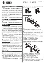
4.1 Fixing the push button
The push button for the remote escape release can be fixed to the outside or inside
of the profile or of a wall.
Fixing to the outside of the profile
Fixing to the inside of the profile
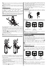
4.1.1. Fixing to the outside of the profile
A
B
C
D
E
F
G
H
a
b
A = Internal mechanism. B = M5 screws (not supplied). C= Outer plastic cap.
D = Fixing profile. Distance a = 19 mm. Distance b = 50 mm. E = Descriptive label
(sold separately).
F = lock nut. G = mushroom button. H = sliding bolt
Attention: Always fix the device with 4 screws. Always use M5 flat-bottom screws
with a resistance class of 4.6 or higher. Install the screws with medium resistance
thread lock, and a number of threads engaged equal to or greater than the screw
diameter. The device must never be fixed with less than 4 screws.
1) Fix the internal mechanism (A) to the machine profile (D). The tightening torque of
the M5 screws (B) must be between 2 and 3 Nm.
2) Fix the actuation cable to the internal mechanism (see paragraph iNSERTiNG THE
CABLE iNTo THE PuSH BuTToN).
3) Attach the outer cap (C) with snap-on coupling.
4) Affix the optional label with the description of the control (E).
5) Put the lock nut (F) on with a tightening torque of between
2 and 3 Nm.
6) Screw the mushroom button (G) onto the sliding bolt (H) with a tightening torque of
between 4 and 5 Nm. During the operation, hold the sliding bolt (H) with a spanner
in order to avoid twisting the sliding bolt (H)
4.1.2. Fixing to the inside of the profile
A
B
C
D
E
F
A = Internal mechanism. B = Fixing profile with Ø 22 mm hole according to
EN 60947-5-1.
C = Descriptive label (sold separately). D = lock nut. E = mushroom
button.
F = sliding bolt.
1) Insert the internal mechanism (A) into the perforated profile (B).
2) Fix the actuation cable to the internal mechanism (see paragraph iNSERTiNG THE
CABLE iNTo THE PuSH BuTToN).
3) Insert the optional label with the description of the control (C).
4) Put the lock nut (D) on with a tightening torque of between
2 and 3 Nm.
5) Screw the mushroom button (E) onto the sliding bolt (F) with a tightening torque of
between 4 and 5 Nm. During the operation, hold the sliding bolt (F) with a spanner
in order to avoid twisting the sliding bolt (F)
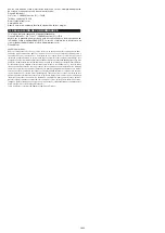
Attention: A distance of between 10 and 35 mm must be maintained between
the push button and the wall from which the button protrudes in order to guarantee
correct operation and easy resetting.


