Pizzato Elettrica Srl
via Torino, 1
36063 MAROSTICA (VI)
ITALY
e-mail: [email protected]
web site: www.pizzato.com
Phone: +39.0424.470.930
ZE FOG47A19-EU
4/12
1 INFORMATION ON THIS DOCUMENT
1.1 Function
The present operating instructions provide information on installation, connection and
safe use for the following articles:
CS AR-94••••.
1.2 Target audience
The operations described in these operating instructions must be carried out by quali-
fied personnel only, who are fully capable of understanding them, and with the techni-
cal qualifications required for operating the machines and plants in which the safety
devices are to be installed.
1.3 Application field
These instructions apply exclusively to the products listed in paragraph Function, and
their accessories.
1.4 Original instructions
The Italian language version is the original set of instructions for the device. Versions
provided in other languages are translations of the original instructions.
2 SYMBOLS USED
This symbol indicates any relevant additional information
Attention: Any failure to observe this warning note can cause damage or mal-
function, including possible loss of the safety function.
3 DESCRIPTION
3.1 Device description
The safety device described here is defined as a logic component for safety functions
according to Machinery Directive 2006/42/EC as well as a safety module for lifts by
the Lift Directive 2014/33/EU.
Upon opening of at least one channel, the safety function ensures that the safety
relays must open their output contacts within the defined reaction time. The safety
outputs of the module are enabled only if the channels CH1 and CH2 are consistently
closed and after activating the START signal.
3.2 Device functions
This device is only suitable for the following applications: as a module for levelling
and re-levelling with open doors, for detecting uncontrolled movements of the cabin
and controlling a device for stopping the cabin, for monitoring the proper actuation and
release of the motor brake, for detecting uncontrolled movements of the cabin during
levelling with open doors and control of a device for stopping the cabin acc. to EN 81-
20:2014, in safety circuits up to category 4 acc. to EN ISO 13849-1, up to SIL 3 acc. to
EN 62061 and up to PL e acc. to EN ISO 13849-1.
- Input with 1 or 2 channels.
- The SIL 3 / PL e safety function is only available with the two redundant inputs
configuration.
- Output contacts: 2 NO safety contacts.
- Choice between automatic start, manual start or monitored start.
With reference to the "automatic" operating mode, consider RES 1.2.3 of the
Machinery Directive 2006/42/EC: "For machinery functioning in automatic mode, the
starting of the machinery, restarting after a stoppage, or a change in operating condi-
tions may be possible without intervention, provided this does not lead to a hazardous
situation".
- Connection of input channels of opposite potentials.
- Can be connected to semiconductor outputs and to magnetic safety sensors.
- Short circuit detection function of the control elements by means of safety system
with self-monitoring and redundancy.
- LED indicators for switching state of the channels 1, 2 and for the power supply
voltage.
- Without muting input, no bridging of the safety function.
- In the event of a failure, the device switches to a safe state and deactivates the
safety output.
- Screw terminals or plug-in terminals with screw connections or spring terminals (de-
pending on the model).
- Snap-mounting on DIN rails.
3.3 Intended use of the device
- The device described in these operating instructions is designed to be applied on
industrial machines.
- The direct sale of this device to the public is prohibited. Installation and use must be
carried out by qualified personnel only.
- The use of the device for purposes other than those specified in these operating
instructions is prohibited.
- Any use other than as expressly specified in these operating instructions shall be
considered unintended by the manufacturer.
- Also considered unintended use:
a) using the device after having made structural, technical, or electrical modifications
to it;
b) using the product in a field of application other than as described in paragraph
TECHNICAL DATA.
4 OPERATION
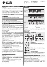
4.1 Operating diagram
Automatic
start:
A1/A2
S11/S12
S21/S22
13/14, 23/24
t
C
t
A
t
R1
t
R1
t
C
t
A
t
R
t
A
Monitored
start:
A1/A2
S11/S12
S21/S22
S33/S34 (START)
13/14, 23/24
t
A
t
R1
t
R1
t
A
t
R
t
MIN
t
A
Manual start:
A1/A2
S11/S12
S21/S22
S33/S34 (START)
13/14, 23/24
t
A
t
R1
t
R1
t
A
t
R
t
MIN
Legend:
t
MIN
:
Min. duration of start impulse
t
C
:
Simultaneity time
t
A
:
Response time
t
R1
:
Release time
t
R
:
Release time in absence of power
supply
Notes: The configurations with one channel are obtained taking into consideration the
S11/S12 input only. In this case it is necessary to consider time t
R1
referred to input
S11/S12, time t
R
referred to the supply, time t
A
referred to input S11/S12 and to the
start, and time t
MIN
referred to the start.
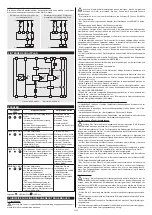
4.2 Wiring diagrams
Input configuration with magnetic sensors
1 channel
2 channels
S31
S33
S21
S22
S11
S35
S34
S12
CS AR-94
A1
A2
L / +
N / -
S31
S33
S21
S22
S11
S35
S34
S12
A1
A2
L / +
N / -
CS AR-94
S34
S34
Automatic start
With regard to the indicated diagrams, short-circuit the S33
and S34 terminals in order to activate the automatic start
module.
S21
S22
S21
S22
S35
S35
Monitored start
With regard to the indicated diagrams, remove the connec-
tion between the S22 and S35 terminals in order to activate
the monitored start module.
Electromechanical switches
The safety module can control both magnetic sensors and
electromechanical switches. Replace the sensor contacts
with switch contacts.
4.3 Short interruptions and voltage variations
The safety module has a built-in sensor that keeps the internal switching state of
the safety relay constant in the event of brief voltage drops to prevent inconsistent
switching states with respect to the status of the inputs. When voltage is restored,
the device continues to operate with a switching state that is consistent with the input
signals.
In the event of brief interruptions or failure of the supply voltage, the safety module
maintains its normal operating functions.
In the event of longer interruptions of the supply voltage, the safety module opens
the safety outputs: for the configuration with automatic start, the safety outputs are
automatically activated when voltage is restored; for manual or monitored start, a
system reset by the operator is required.

