background image

L80-029 Rev 5  10/07                                                          8

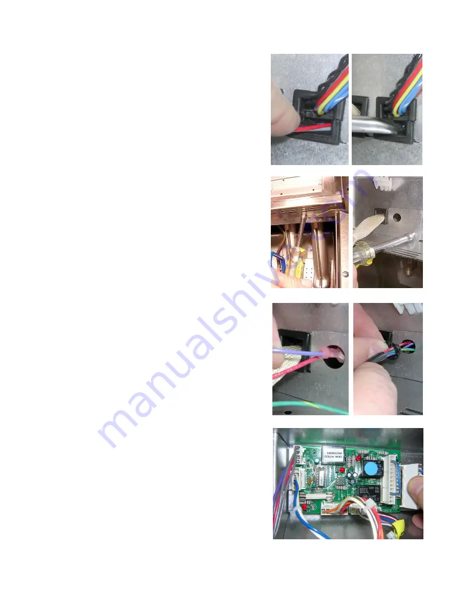
e.  If the appliance you are upgrading does NOT have a

Solid State Control, proceed to step f in this section.
If the appliance that you are upgrading has a Solid
State Control, feed the other ends of the SCBS
Harness through the unused portion of the strain
relief holding the Solid State Control Harness and
proceed directly to step h in this section.

NOTE:

 If needed, you can carefully nudge open the

area in the strain relief with a screwdriver to make
additional room to insert the SCBS harness. Take
care not damage the harness during this procedure.

f. 

Using a 5/16 nut driver, remove the two screws on
the underside of the front panel that hold the slotted
bottom on. Remove the slotted front panel bottom;
this will allow easier access to the cable retainer
plate. Remove the two screws holding the cable
retainer plate onto the appliance and remove the
cable retainer plate, leaving the control cable held in
place by the square strain relief.  Replace the cable
retainer plate that you removed with the new one
provided in the kit. Cable retainer plate style varies
from model to model; the one that came with your kit
should look exactly like the one that you removed
with an added hole.

g.  Feed the SCBS harness through the hole in the cable

retainer plate. Collect and capture all wires in this
harness into the split grommet provided with the kit
and install the grommet into hole in the cable retainer
plate. The installation of the grommet is critical as it
insures that the wires will not chafe and/or short out
against the metal edge of the hole in the cable
retainer bracket.

h.  You may now reconnect the main control harness to

the SCBS board exactly as it was connected to the
previous board, re-attach the front panel bottom and
reconnect, remount and close up the front panel
assembly.

Summary of Contents for L80-029

Page 1: ...on and retain these instructions for the life of the equipment Model __________________________ Serial __________________________ Date Upgraded ___________________ Technician _________________________ Installation Instructions for the PITCO Self Cleaning Burner System E N G L I S H ...

Page 2: ...kit should only be performed by a competent service technician WARNING Do not attempt to move a cooking appliance when the unit is at operating temperature Serious personal injury could result if skin comes in contact with the hot surfaces WARNING DO NOT sit or stand on this appliance Serious injury could result from falling or contact with hot shortening oil WARNING Improper installation alterati...

Page 3: ... face by incinerating any foreign matter that has accumulated from the previous day s operation The Pitco Self Cleaning Burner System is designed to help maintain proper operation and efficiency of your appliance s combustion system by minimizing the build up of any foreign material inside the burner housings Proper installation of this upgrade and periodic maintenance of the appliance are critica...

Page 4: ...onnect the control harness and tuck it out of the way to avoid damaging the harness during this procedure Be sure to store the control in a safe place to avoid accidental damage to it c Using a 7 16 wrench remove the pilot tubing from the gas valve by turning the brass fitting counter clockwise There is no need to remove the pilot from the burner assembly WARNING Ensure that the tank contents have...

Page 5: ...r head WARNING Be sure to keep the removed burners separate from burners supplied with the upgrade kit The existing burners WILL NOT work with the Pitco Self Cleaning Burner System DO NOT attempt to use the old burners with the Pitco Self Cleaning Burner System an unsafe condition may occur g Replace the burners to the LEFT of the pilot with burners supplied with the Pitco Self Cleaning Burner Sys...

Page 6: ...re installed correctly Improperly mounted or poorly aligned burners may result in an unsafe condition or poor appliance performance They should be mounted properly on the orifice fittings facing straight into the burner tubes and secured tightly to the appliance Follow this procedure for installation of the SCBS Valve NOTE The valve type you receive in your kit may differ in appearance slightly fr...

Page 7: ...ng to ensure a gas tight seal NOTE The threads on this fitting 1 8 NPT and compression are not interchangeable Be sure to install the NPT side of this fitting into the gas valve Failure to complete this step correctly could damage the threads of both the fitting and the pressure test port and may result in gas leakage at this joint c Remove the 1 8 NPT X 90 compression fitting from the other end o...

Page 8: ... Reinstall the pilot tubing into the gas valve h Reconnect the control harness to the main gas valve and if you removed a Solid State Control earlier in this procedure you may re install it at this time Follow this procedure to prepare and install the SCBS Control Board and Harnesses a Using a phillips head screwdriver remove the two screws that secure front panel and rotate the control assembly d...

Page 9: ...ined into one single harness NOTE It is critical for proper operation that the insulation paper is installed Failure to install the insulation paper may cause soldered joints on the back of the Control board to short out and damage the Control board and or appliance d Plug four pin connector on SCBS Harness into SCBS Relay Board and ground as shown using the existing fastener to secure ground cabl...

Page 10: ...ws holding the cable retainer plate onto the appliance and remove the cable retainer plate leaving the control cable held in place by the square strain relief Replace the cable retainer plate that you removed with the new one provided in the kit Cable retainer plate style varies from model to model the one that came with your kit should look exactly like the one that you removed with an added hole...

Page 11: ...nt of the appliance Mount the assembly by straddling it on the two burners on either side of the pilot and positioned up to where the flange on the assembly meets with the bottom of the flange on the burner web see photos at right l Fasten the Thermal Limit Switch to the flange on the burner web using two self drilling fasteners provided in the Pitco Self Cleaning Burner System Kit Connect the lea...

Page 12: ... at the main burner orifice of each burner Interwaiting period 2 8 seconds The Main and SCBS valves de energize for this period The pilot remains lit Normal operation resumes N A The appliance operates normally and begins to heat up The SCBS Valve remains de energized until power to the appliance is recycled There is no flame on the SCBS Arm There is no burn at the main burner orifices With the Pi...

Page 13: ... these instructions If there appears to be significant roll out during ignition or any time during operation proceed to step d of this section of these instructions c For pulsing lifting burner flame Turn the appliance off and allow it to cool Pull the appliance out from under the hood and loosen the screws securing the adjustable slide plate on the flue baffle Move the slide plate toward the rear...

Page 14: ...ation Refer to flue baffle adjustment procedure in these instructions to set flue baffle to a less restrictive setting Model MG2 or MG2T flue baffle is set too restrictively Faulty hi limit switch Appliance will not maintain temperature properly Refer to Service and Parts manual to diagnose this problem and replace temperature probe Refer to Service and Parts manual to diagnose this problem and re...

Page 15: ...13 L80 029 Rev 5 10 07 ...

Page 16: ...L80 029 Rev 5 10 07 14 ...

Page 17: ...15 L80 029 Rev 5 10 07 ...

Page 18: ...L80 029 Rev 5 10 07 16 ...

Page 19: ...17 L80 029 Rev 5 10 07 ...

Page 20: ...L80 029 Rev 5 10 07 18 ...

Page 21: ...19 L80 029 Rev 5 10 07 ...

Page 22: ...L80 029 Rev 5 10 07 20 ...

Page 23: ... the installation of the SCBS upgrade Wire harnesses and pilot tubing are omitted to provide better clarity In order to give the installer a sense of part orientation and location the gas piping parts valve tubing runner arm and fittings of the SCBS system are shaded For clarity the thermal limit switch assembly is not shaded ...

Page 24: ... about your order please contact the Pitco Frialator factory at 800 258 3708 US and Canada only or 603 225 6684 World Wide In the event of problems with or questions about your equipment please contact the Pitco Frialator Authorized Service and Parts representative ASAP covering your area or contact Pitco at the numbers listed to the left ...

Reviews: