XV-EV51
109
5
6
7
8
5
6
7
8
C
D
F
A
B
E
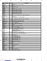
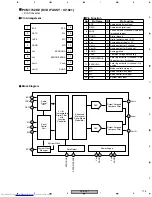
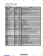
Pin Function
No.
Pin Name
I/O
Pin Function
1
FP_SO
OUT
Front Panel interface. (Soft) Serial transfer data output.
2
A_DATA3
OUT
Reserved
3
XAMUTE
OUT
Analog audio output line muteing output 'L'.
4
VDD_3V3
−
3.3 V Power supply
5
VSS
−
Ground
6
AQE_XCS
OUT
Reserved
Audio Quality Enhancer IC's chip-select output.
7
SQUEEZ
OUT
S-Video output S1/S2 control signal at squeez output mode 'H'.
8
LETTER
OUT
S-Video output S1/S2 control signal & EURO(SCART) connecter (FUNCTION SWITCHING) signal at
letter-box output mode 'H'.
9
TRYPOS
OUT
In case of NOT carusel 5 disc changer, this port is N.C.(output)
TRYPOS
IN
Carousel 5 Disc Chenger only
Tray rotete puls input.
Capture function can be used.
10
V_SEL1
OUT
For EURO(SCART) connecter (BLINKING) signal
'L' : RGB output disable 'H' : RGB output enable
11
RTS
OUT
UART(RS-232C) Request To Send signal output.
12
V_SEL2
OUT
For EURO(SCART) connecter V/Y, R/C signal select
'L' : VRGB output = VRGB 'H' : VRGB output = YCGB
13
CTS
IN
UART(RS-232C) Clear To Send signal input.
14
VDD_2V5
−
2.5 V Power supply
15
VSS
−
Ground
16
FE_DATA
IN
Front-End L6315 stream interface.
Searial data input.
17
FE_BCLK
IN
Front-End L6315 stream interface.
Searial clock input.
18
FE_DVALID
IN
Front-End L6315 stream interface.
Data valid flag input.
19
FE_SYNC
IN
Front-End L6315 stream interface.
Searial synchronize flag input.
20
FE_EVALID
IN
Front-End L6315 stream interface.
If STi5588 then RS-SPLIT error valid flag.
21
FE_ECCBST
IN
Front-End L6315 stream interface.
If STi5588 then RS-SPLIT ECC Block Start flag.
22
TP- ( VQE_XCS )
OUT
Reserved
23
VDD_RGB
−
RGB circuit 2.5 V Power supply
24
VSS_RGB
−
RGB circuit Ground
25
B_OUT
OUT
B / Cb
26
G_OUT
OUT
G / Y
27
RC_OUT
OUT
R / Cr
28
VREF_RGB
IN
RGB DAC reference
29
IREF_RGB
IN
RGB DAC electric current reference
30
VDD/YCC
−
YC circuit 2.5 V Power supply
31
VSS_YCC
−
YC circuit Ground
32
Y_OUT
OUT
Y
33
C_OUT
OUT
C
34
CV_OUT
OUT
CV
35
VREF_YC
IN
YCC DAC reference


