8
XV-BD422B
1
2
3
4
A
B
C
D
E
F
1
2
3
4
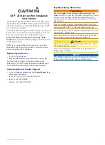
4. BLOCK DIAGRAM
4.1 OVERALL WIRING DIAGRAM
XP5
XP4
1
J
6
J
7
J
5
R
_
X
U
A
5
GND
L
_
X
U
A
3
A
C
R
J4
J5
GND
P2
1
CVBS_O
1
XP7
45
1
XP10
8
TPIC_A-
TPIC_B-
U/C
V/W
W/V
C/U
1
XP5
TPIC_TRAYIN# 4
MGND
TP
TPIC_LOAD-
1
7
1
P
X
3
1
P
X
6
1
P
X
1
0
2
1
4
1
GN
D
US
BP
1
US
BM1
WIFI_
V
C
C
VO
L
+
VO
L
-
KE
Y
1
KE
Y
2
P
-24V
GN
D
+12V
_D
GN
D
ST
B
Y
_3V
3
SP
I_C
L
K
SP
I_DA
T
SP
I_C
S
IR
_
IN
PW
M
_
L
E
D
GN
D
MP
3
_
L
GN
D
MP
3
_
R
GN
D
MIC
US
B_
V
C
C
1
GN
D
US
BM2
US
BP
2
US
BM0
6
0
2
1
6
0
6
S
X
3
P
X
4
1
JACK603
JA
P801
P8
USB1
US
AUX R
AUX L
CVBS
Optical
IN 1
Optical
IN 2
HDMI IN 2
HDMI IN 1
HDMI OUT
LAN (10/100)
MIC
P
MAIN BOARD ASSY
(08-H555DU-MA1R/YXV)
NOT USED
A
FRONT BOARD ASSY
(08-BCS727-FVY)
B
AV BOARD ASSY
(AZW7613)
D
A
1/13-
A
13/13
LOADER ASSY
(08-LTCA19-222026)
Wi-Fi MODULE
Summary of Contents for XV-BD122B
Page 34: ...34 XV BD422B 1 2 3 4 A B C D E F 1 2 3 4 9 2 EXTERIOR SECTION K K A B A B C C B A G J J G ...
Page 37: ...37 XV BD422B 5 6 7 8 5 6 7 8 A B C D E F ...
Page 73: ...73 XV BD422B 5 6 7 8 5 6 7 8 A B C D E F ...
Page 79: ...79 XV BD422B 5 6 7 8 5 6 7 8 A B C D E F XP10 XP5 XP16 XP7 SIDE B A Q102 ...
Page 81: ...81 XV BD422B 5 6 7 8 5 6 7 8 A B C D E F SIDE A SIDE B B Q141 ...