92
XR-A550MD
No.
Pin Name
I/O
Function
No.
Pin Name
I/O
Function
1
O
GND
41
JOG2
I
JOG2 input
2
O
NC
42
JOG1
I
JOG1 input
3
O
NC
43
S.REQ
I/O
System bus request
4
O
NC
44
S.DATA OUT
O
System bus data output
5
I
Pull up
45
S.DATA IN
I
System bus data input
6
O
NC
46
O
NC
7
O
NC
47
XMUTE
O
Line mute
8
O
NC
48
DSCK
O
MD unit communication clock
9
O
NC
49
MDDAT
I
MD unit
→
System control data
10
O
NC
50
KDAT
O
System control data
→
MD unit
11
O
NC
51
FL CP
O
FL driver clock
12
O
NC
52
MDST
O
MD unit ON
13
O
NC
53
FL DATA
O
FL driver data
14
O
NC
54
LOAD
I
Load-in detection
15
O
NC
55
DSTB
I
MD unit communication strobe
16
O
NC
56
I
Pull up
17
CDDIG
O
Digital in CD
57
I
Pull up
18
AUXDIG
O
Digital in AUX
58
O
NC
19
O
NC
59
O
NC
20
O
NC
60
S.CLK
I
System bus clock
21
O
NC
61
XREC MUTE
O
REC mute
22
O
NC
62
MDRST
O
MD unit reset
23
O
NC
63
SERCH
O
Cut in rehearsal pause request
64
ACDET
I
Power failure detection
65
6.5/5
O
NC
Transmit the power failure to the MD unit
66
O
NC
67
O
NC
68
O
NC
69
O
NC
MD microcomputer reset terminal
70
O
NC
Connect the oscillator (8.38MHz)
71
O
NC
72
Vdd
−
33 Vss
−
73
NC
−
34
TX
O
74
O
NC
35
TEX
I
75
O
NC
36
AVss
−
A/D converter GND
76
O
NC
37
AVref
I
Reference voltage of A/D conversion
77
O
NC
38
KEY
I
Key input (A/D conversion)
78
O
NC
39
I
NC
79
O
NC
40
XTEST1
I
Test terminal 1
80
O
GND
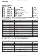
7. GENERAL INFORMATION
• The information shown in the list is basic information and may not correspond exactly to that shown in the schematic diagrams.
PDG244A (MD MAIN ASSY : IC4502)
• MD Control Microcomputer
•
Pin Function
7.1 PARTS
7.1.1 IC
www. xiaoyu163. com
QQ 376315150
9
9
2
8
9
4
2
9
8
TEL 13942296513
9
9
2
8
9
4
2
9
8
0
5
1
5
1
3
6
7
3
Q
Q
TEL 13942296513 QQ 376315150 892498299
TEL 13942296513 QQ 376315150 892498299


