
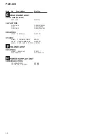


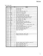


63
PDR-609
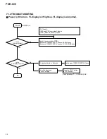
<Pickup replacement repair, the final check inspection method after adjustment>
Disc required:
CD-R disc
* [STD-R07(PVC:RDD-74B,RDD-74BJ)]
[STD-R08(PVC:RDD-74,RDD-74U)]
or equivalent
CD-RW disc
* [STD-R11(PVC:RDW-74,RDW-74J)]
or equivalent
[Inspection items]
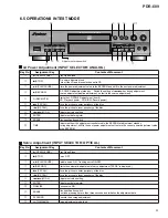
1. Recording-playback jitter
Method: Measure RF signal (CN102-pin2) by Jitter Meter (Trailing edge).
Specification: 35nS or below.
2. Recording-playback block error
Method: While pushing "MENU/DELETE" key, press "MONITOR" key.
Display: appears in about 4 sec like C1 * * * * *
Specification: 65 pieces or less
(Press "STOP" key to reset display)
3. Recording-playback ATIP error
Method: While pushing "MENU/DELETE" key, press "DISPLAY/CHARA" key.
Display: appears in about 10 sec like ATIP * * * * * *
Left 3 digit datum = Total number of errors
Right 3 digit datum = Maximum continuous error number (Specification item)
Specification: Max continuous error (Right side datum) must be 7 pieces or less.
(Press "STOP" key to reset display)
[Warning]
Scratch, dust, fingerprint, etc. on recording disc may cause deterioration of performance. Be careful no to be occurred.
When CD-RW disc is used for measurement, do not use the same position at more than 100 times.
Summary of Contents for PDR-609
Page 45: ...PDR 609 45 A B C D 5 6 7 8 5 6 7 8 G IC701 IC702 IC706 CN601 D SIDE A SIDE B ...
Page 73: ...73 PDR 609 Pin Function 2 5 ...
Page 74: ...74 PDR 609 Pin Function 3 5 ...
Page 75: ...75 PDR 609 Pin Function 4 5 ...
Page 76: ...76 PDR 609 Pin Function 5 5 ...
Page 80: ...80 PDR 609 AK8567 CD R CORE PCB ASSY IC101 RF Processor Pin Function 1 2 ...
Page 81: ...81 PDR 609 Pin Function 2 2 ...
Page 84: ...84 PDR 609 1 FL TUBE Grid Assignment Pin Connection PEL1101 OPERATING ASSY V701 7 2 2 DISPLAY ...
Page 85: ...85 PDR 609 Anode Connection ...