


PDR-609
31
A
B
C
D
5
6
7
8
5
6
7
8
2/2
D
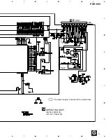
CN601
CN602
D
1/2
A
1/5
CN701
CN302
G
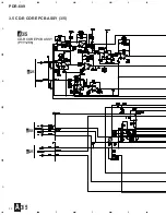
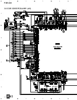
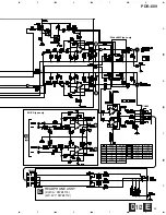
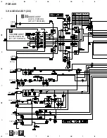
: The power supply is shown with the marked box.
SIGNAL ROUTE
: AUDIO SIGNAL
: AUDIO SIGNAL (REC)
: OPTICAL SIGNAL
: COAXI AL SIGNAL
(OP)
(R)
(CO)
(OP)
(OP)
(OP)
(OP)
(CO)
(CO)
(R)
(R)
(R)
KU/CA
type only
KU/CA
type only
WV, WY
type only
Summary of Contents for PDR-609
Page 45: ...PDR 609 45 A B C D 5 6 7 8 5 6 7 8 G IC701 IC702 IC706 CN601 D SIDE A SIDE B ...
Page 73: ...73 PDR 609 Pin Function 2 5 ...
Page 74: ...74 PDR 609 Pin Function 3 5 ...
Page 75: ...75 PDR 609 Pin Function 4 5 ...
Page 76: ...76 PDR 609 Pin Function 5 5 ...
Page 80: ...80 PDR 609 AK8567 CD R CORE PCB ASSY IC101 RF Processor Pin Function 1 2 ...
Page 81: ...81 PDR 609 Pin Function 2 2 ...
Page 84: ...84 PDR 609 1 FL TUBE Grid Assignment Pin Connection PEL1101 OPERATING ASSY V701 7 2 2 DISPLAY ...
Page 85: ...85 PDR 609 Anode Connection ...