71
PDR-609
1
Remove the CD-R CORE Assy. (Refer to the Disassembly of the CD-R CORE Assy and steps to of the Servo
Mechanism Block.
2
Replace seven cables ( ~ ) for service and diagnose it.
CD-R CORE PCB Assy
CN901
↔
CN202 (POWER SUPPLY Assy)
Connector Assy (6P) : PG06KK-F50
CN452
↔
CN601 (Servo Mechanism Assy)
8P FFC : PDD1225
1
2
3
CN502
↔
CN401 (AUDIO Assy)
25P FFC : PDD1227
4
3
CN302
↔
CN602 (AUDIO Assy)
9P FFC : PDD1226
5
CN101
↔
CN1 (Pickup)
32P FFC : PDD1224
6
CN451
↔
CN101 (LOAB Assy)
Connector Assy (3P) : PG03KK-50
1
7
CD-R CORE PCB Assy
↔
Other Assys
7.1.6 DIAGNOSIS OF CD-R CORE ASSY
When diagnosing the CD-R CORE Assy, use the following Flexible Cables and Connector Assys for service.
• Flexible Cables and Connector Assys for service
1
6
Servo Mechanism Assy
AUDIO Assy
POWER SUPPLY Assy
Unhook
Unhook
9
8
×
2
Rear side
•Bottom view
4
1
2
6
5
CN101
CN451
CN452
CN901
CN302
CN502
CN401
CN602
CN202
Summary of Contents for PDR-609
Page 45: ...PDR 609 45 A B C D 5 6 7 8 5 6 7 8 G IC701 IC702 IC706 CN601 D SIDE A SIDE B ...
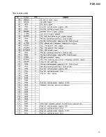
Page 73: ...73 PDR 609 Pin Function 2 5 ...
Page 74: ...74 PDR 609 Pin Function 3 5 ...
Page 75: ...75 PDR 609 Pin Function 4 5 ...
Page 76: ...76 PDR 609 Pin Function 5 5 ...
Page 80: ...80 PDR 609 AK8567 CD R CORE PCB ASSY IC101 RF Processor Pin Function 1 2 ...
Page 81: ...81 PDR 609 Pin Function 2 2 ...
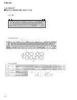
Page 84: ...84 PDR 609 1 FL TUBE Grid Assignment Pin Connection PEL1101 OPERATING ASSY V701 7 2 2 DISPLAY ...
Page 85: ...85 PDR 609 Anode Connection ...


