


10
<ARE1357>
En/Fr/Ge
PANEL FEATURES AND FUNCTIONS
CARACTERISTIQUES ET FONCTIONS DES PANNEAUX
TASTEN, EINSTELLUNGEN UND FUNKTIONEN
VD
HD
B
G
R
C
Y
OUT
IN
75
2.2k
OFF
ON
(
Ω
)
(H/V SYNC) RGB-1 (ON SYNC)
Y/C
SYNC
REMOTE
G ON SYNC
VIDEO
RS-232C
RGB-2
OFF
ON
8 9
7
-
0
= ~ ! @ # $ % ^
&
(
*
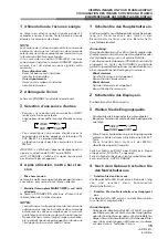
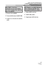
<Rear Panel Terminals/Con-
nections to Power Source>
RGB-2 input terminals
7
Remote control out switch (ON/
OFF)
This switch will output remote
control commands from the
RGB-2 (D-SUB 15-pin) terminal
to control external peripheral
devices planned for future sales
release. Normally be sure to
use set to OFF.
8
MINI D-SUB 15-pin terminal
9
G on Sync mode selection
switch (ON/OFF)
If the images become greenish
when an external device is con-
nected to the RGB-2 input ter-
minal, turn ON the G on SYNC
mode. Normally set to OFF.
RGB-1 input terminals
0
Sync Signal Input Impedance
switch (75
Ω
/2,2 k
Ω
)
-
Vertical Sync Signal Input ter-
minal: (75
Ω
/2,2 k
Ω
, switchable
with the Sync Signal Input Im-
pedance switch)
=
Horizontal or Composite Sync
Signal Input terminal: (75
Ω
/2,2
k
Ω
, switchable with the Sync
Signal Input Impedance switch)
~
Blue Signal Input terminal: 75
Ω
!
Green or Green with Sync Sig-
nal Input terminal (ON SYNC):
75
Ω
@
Red Signal Input terminal: 75
Ω
Y/C input terminals
#
Color Signal Input terminal: 75
Ω
$
Luminance Signal Input termi-
nal: 75
Ω
VIDEO input/output terminals
%
Video Output terminal: 75
Ω
^
Video Input terminal: 75
Ω
&
Control Signal Input terminal
(RS-232C compliance)
*
AC inlet
(
MAIN POWER switch
<Bornes du panneau arrière/
Connexions à la source
d’alimentation>
Bornes d’entrée RGB-2
7
Contacteur d’émission de
commandes à distance (ON/OFF
= MARCHE/ARRET)
Ce contacteur émet les
commandes à distance en prov-
enance de la borne RGB-2 (D-SUB
15 broches) vers les périphériques
externes qui seront vendus à
l’avenir.
S’assurer que le réglage est sur
OFF.
8
Borne 15 broches MINI D-SUB
9
G sur bouton de sélection du
mode Sync (ON/OFF = MARCHE/
ARRET)
Si les images deviennent verdâtres
lorsqu’un dispositif extérieur est
raccordé au terminal d’entrée
RGB-2, amener G sur le mode
SYNC. Normalement, celui-ci est
réglé sur OFF (= arrêt).
Bornes d’entrée RGB-1
0
Commutateur d’impédance
d’entrée du signal de
synchronisation (75
Ω
/2,2 k
Ω
)
-
Borne d’entrée du signal de
synchronisation vertical (75
Ω
/2,2
k
Ω
, commutable avec le
commutateur d’impédance
d’entrée du signal de
synchronisation)
=
Borne d’entrée du signal de
synchronisation horizontal ou
composite : (75
Ω
/2,2 k
Ω
, commut-
able avec l’interrupteur
d’impédance d’entrée du signal de
synchronisation)
~
Borne d’entrée du signal bleu: 75
Ω
!
Borne d’entrée du signal vert ou
vert avec signal de synchronisation
(ON SYNC) : 75
Ω
.
@
Borne d’entrée du signal rouge :
75
Ω
Bornes d’entrée Y/C
#
Borne d’entrée du signal couleur:
75
Ω
$
Borne d’entrée du signal de lumi-
nance : 75
Ω
Bornes d’entrée/sortie VIDEO
%
Borne de sortie vidéo : 75
Ω
^
Borne d’entrée vidéo : 75
Ω
&
Borne d’entrée du signal de
commande (Conforme au stan-
dard RS-232C)
*
Prise c.a.
(
Interrupteur général POWER
<Anschlußleiste>
RGB 2-Eingang
7
EIN-/AUS-Schalter der
Fernbedienung (ON/OFF)
Mit diesem Schalter können
Fernbedienungsbefehle über
den Anschluß RGB-2 (D-SUB,
15-Pin-Buchse) ausgegeben
werden, um zukünftiges
Zubehör zu steuern.
Für den Normalbetrieb
unbedingt auf OFF stellen.
8
MINI D-SUB 15-Pin-Eingang
9
G an Sync-Moduswählschalter
(ON/OFF)
Wird der Bildschirm grünlich,
sobald ein externes Gerät an der
Input-Schnittstelle von RGB - 2 -
angeschlossen wird, schalten Sie
G am Sync-Moduswählschalter
auf ON (EIN), während es
normalerweise auf OFF (AUS)
steht.
RGB 1-Eingang
0
S y n c h r o n s i g n a l - E i n g a n g s -
Impedanz-Schalter (75
Ω
/2,2 k
Ω
).
-
Vertikaler Synchronsignal-
Eingang (75
Ω
/2,2 k
Ω
, einstellbar
mit dem Synchronsignal-
Eingangs-Impedanz-Schalter).
=
Horizontaler oder kombinierter
Synchroneingang: (75
Ω
/2,2 k
Ω
,
einstellbar mit dem
S y n c h r o n s i g n a l - E i n g a n g s -
Impedanz-Schalter).
~
Blaues Signal: 75
Ω
!
Grünes Signal oder Grün mit
Synchronsignal-Eingang (ON
SYNC): 75
Ω
@
Rotes Signal: 75
Ω
Y/C Eingang
#
Farbsignal Eingang: 75
Ω
$
Helligkeitssignal-Eingang: 75
Ω
VIDEO-Eingang/Ausgang
%
Video-Ausgang: 75
Ω
^
Video-Eingang: 75
Ω
&
Kontrollsignal-Eingang (RS-
232C kompatibel)
*
Netzanschluß
(
Netzschalter (MAIN POWER)
<Rear Panel Terminal/Connections to Power Source>
<Bornes du panneau arrière/Connexions à la source d’alimentation>
<Hintere Anschlußleiste / Netzanschluß>