MVH-X580BS/XNUC
5
5
6
7
8
5
6
7
8
C
D
F
A
B
E
1.4 NOTES ON REPLACING PARTS
1.5 OTHERS
Be careful in handling ICs. Some ICs such as MOS type are so fragile that they can be damaged by electrostatic
induction.
Please be careful of not to apply static charge onto integrated circuits, etc, when you conduct repair work.
Especially, please use soldering iron with its tip grounded.
Also, please use a pair of tweezers with static charge protection capability if there is the possibility of contacting to
device terminals, and avoid the use of metal-made tweezers.
The part listed below is difficult to replace as a discrete component part.
When the part listed in the table is defective, replace whole Assy.
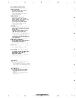
Notes about installation and pin number description of Power IC (IC1301: PA2032A)
The Power IC, PA2032A used on the Tuner Amp Unit is a 25 pin IC.
The same PCB of the Tuner Amp Unit is used for other models that use a 27 pin IC, too.
So, the PCB has lands for a 27 pin IC.
When you replace the Power IC, install the Power IC onto 25 pins (2- 26 pin) located in the center of 27 pins for IC301.
Therefore, when you check the Power IC on the schematic diagram and the PCB connection diagram, you have to pay
attention as follows.
BGA
BGA
Heat pad
Heat pad
IC501
U1001
IC201
IC751
STA1080
CWX4751
BD49101AEFS
PM9015A
SYSTEM MICROCOMPUTER
BT MODULE
SYSTEM POWER SUPPLY
E-VOL
SCHEMATIC DIAGRAM
The pin number of left side is a number
on the PCB (silk printing).
The pin number of right side (in the IC frame)
means the pin number of IC itself.
No connection
1
2
3
4
5
6
7
8
9
10
11
12
13
14
15
16
17
18
19
20
21
22
23
24
25
No connection
IC1301
For environmental protection, lead-free solder is used on the printed circuit boards mounted in this unit.
Be sure to use lead-free solder and a soldering iron that can meet specifications for use with lead-free solders for
repairs accompanied by reworking of soldering.
Notes on soldering


