background image

MVH-X580BS/XNUC

12

1

2

3

4

1

2

3

4

C

D

F

A

B

E

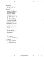
5.3  CONNECTOR FUNCTION DESCRIPTION

  1   SXiL
  2   SXiTX
  3   NC
  4   SXiR
  5   SXiG
  6   SXiRX
  7   NC
  8   GND
  9   SXi PW
10   SXiPW

Sirius XM BUS

FM/AM ANTENNA INPUT

Sirius XM BUS
(MVH-X580BS/XNUC)

WIRED 

REMOTE 

CONTROL

MICROPHONE

INPUT

SUBWOOFER OUTPUT

FRONT

OUTPUT

REAR

OUTPUT

16 14 12 10 8

6 4

2

15 13 11 9

7

5 3

1

1   FL+
2   FR+
3   FL-
4   FR-
5   RL+
6   RR+
7   RL-
8   RR-

  9   NC
10   NC
11   ILL
12   NC
13   ACC
14   B.REM
15   B.UP
16   GND

MVH-X580BS/XNUC
MVH-X580DAB/XNEW5
MVH-X580BT/XNEW5

DAB ANTENNA INPUT
(MVH-X580DAB/XNEW5)

Summary of Contents for MVH-X580BS

Page 1: ...CA 90801 1760 U S A PIONEER EUROPE NV Haven 1087 Keetberglaan 1 9120 Melsele Belgium PIONEER ELECTRONICS ASIACENTRE PTE LTD 2 Jalan Kilang Barat 07 01 Singapore 159346 PIONEER CORPORATION 2016 MVH X580BS XNUC CRT5837 DIGITAL MEDIA RECEIVER MVH X580BS XNUC MVH X580DAB XNEW5 MVH X580BT XNEW5 MVH X585BT XNES K ZZZ MAY 2016 Printed in Japan ...

Page 2: ...d This service manual is intended for qualified service technicians it is not meant for the casual do it yourselfer Qualified technicians have the necessary test equipment and tools and have been trained to properly and safely repair complex products such as those covered by this manual Improperly performed repairs can adversely affect the safety and reliability of the product and may void the war...

Page 3: ...SPLAY TEST MODE 1 15 6 2 DISPLAY TEST MODE 2 16 6 3 SOFTWARE VERSION UP METHOD 17 7 DISASSEMBLY 18 8 EACH SETTING AND ADJUSTMENT 20 9 EXPLODED VIEWS AND PARTS LIST 21 9 1 PACKING 21 9 2 EXTERIOR 23 10 SCHEMATIC DIAGRAM 26 10 1 TUNER AMP UNIT VEHICLE I F 26 10 2 TUNER AMP UNIT SYSTEM REGULATOR 27 10 3 TUNER AMP UNIT DDCON 28 10 4 TUNER AMP UNIT OTHER SUPPLY 29 10 5 TUNER AMP UNIT SYSCOM 30 10 6 TUN...

Page 4: ...ety instructions described in this manual area and a heat sink becomes hot areas Be careful not to burn yourself TUNER AMP UNIT Side B IC201 HEAT SINK Before disassembling the unit be sure to turn off the power Unplugging and plugging the connectors during power on mode may damage the ICs inside the unit Please be sure to conduct line process to original status if you make assembling after repair ...

Page 5: ...of the Tuner Amp Unit is used for other models that use a 27 pin IC too So the PCB has lands for a 27 pin IC When you replace the Power IC install the Power IC onto 25 pins 2 26 pin located in the center of 27 pins for IC301 Therefore when you check the Power IC on the schematic diagram and the PCB connection diagram you have to pay attention as follows BGA BGA Heat pad Heat pad IC501 U1001 IC201 ...

Page 6: ...er the customer complain has been solved If the customer complain occurs with the specific media use it for the operation check The customer complain must not be reappeared Display audio and operations must be normal 2 FM AM tuner Check FM AM tuner action Seek Preset Switch band to check both FM and AM Display audio and operations must be normal 3 receiving it for service See the table below for t...

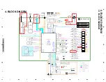
Page 7: ...ABSXI14V RFVCC3 3V IC421 S 1155B33 DD3VON RFVCC3 3V DDC5V IC301 KBD9876EFJ VDDEN DDC5V VDDIO3 3V VDDIO3 3V HIOUT8V IC461 NJW4184DL3 HIOUT_EN HIOUT8V IC201 DD3VON CPPWR BT18EN BTPW EN ECO SYNC USBCTL1 USBCTL2 MUTE KYDT DPDT ROT0 ROT1 USB1_DP USB1_DM X501 32 768KHz TUN3 3V REG3 USB1_5V ILM B Hiside SW USB5V REG4 BSENS ILMPW B Up B Up B Up SSENS AUXL AUXR BTTOSYS SYSTOBT BTCTS BTRTS BTDATAIN BTDATAOU...

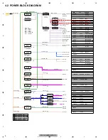
Page 8: ...0 mA 1 000 0 mA USB1 S11 6 STD 6 00 V 2 715 mA Mecha VD 6 0V DDC1 Mecha VD 1 000 0 mA 300 0 mA ILM B SW Hiside SW 220 0 mA K B Illumi RGB 220 mA TC7SET08FUS1 2 0 mA 5 00 5 25 5 50 3 5 IC 10 0 mA 3 0 mA BU97540KV 22 0 mA REG5 10 VDDEN ANTPW RGB model USBCTL1 DTUN1V_ON DTUN3V_ON HIOUTEN REG4EN DTUN1V_ON SXI PWR DAB ANT PW SXI PW 400 mA Power Amp 300 mA 185 mA L101 BUP14 4V VDDIO3 3V VDD1 2V SYS B5 7...

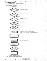
Page 9: ... B15 VDDIO3 3V Pin E6 E7 E8 F7 F8 M6 M14 VDD1 2V Pin E9 E10 F6 F9 G5 N5 N6 N10 N13 SWVDD IC201 Pin1 SYS B5 7V IC201 Pin16 VDDIO_On 3 3V bsens asens dsens VDD1 2V 1 2V VDDIO3 3V 3 3V bsens L asens L Starts communication SOC dsens L SWVDD 5 2V Source ON SYS B5 7V 5 7V Completes power on operation After that proceed to each source operation Power ON VDDEN H VDDEN H Starts communication LCD driver ...

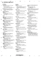
Page 10: ... s main menu is displayed reconnect the device and reset it START UP APP The Pandora application has not started running yet Start up the Pandora application RATING ERROR The thumb rating operation was disabled Run the same command for another track CAN T SKIP The skip operation was disabled Run the same command for another track TRY LATER Unable to save thumb rating Unable to save BookMark Unable...

Page 11: ...that the SiriusXM magnetic mount antenna is mounted on a metal surface on the outside the vehicle Move the SiriusXM antenna away from any obstructions SUBSCRIPTION UPDATED This unit has detected a change in your SiriusXM subscription status Press any key to clear the message CH UNAVAIL The channel that you have requested is not available Check the SiriusXM channel lineup CHAN UNSUB The channel tha...

Page 12: ...s XM BUS FM AM ANTENNA INPUT Sirius XM BUS MVH X580BS XNUC WIRED REMOTE CONTROL MICROPHONE INPUT SUBWOOFER OUTPUT FRONT OUTPUT REAR OUTPUT 16 14 12 10 8 6 4 2 15 13 11 9 7 5 3 1 1 FL 2 FR 3 FL 4 FR 5 RL 6 RR 7 RL 8 RR 9 NC 10 NC 11 ILL 12 NC 13 ACC 14 B REM 15 B UP 16 GND MVH X580BS XNUC MVH X580DAB XNEW5 MVH X580BT XNEW5 DAB ANTENNA INPUT MVH X580DAB XNEW5 ...

Page 13: ... WIRED REMOTE CONTROL MICROPHONE INPUT SUBWOOFER OUTPUT FRONT OUTPUT REAR OUTPUT 16 14 12 10 8 6 4 1 2 3 15 13 11 9 7 5 3 2 1 4 1 FL 2 FR 3 FL 4 FR 5 RL 6 RR 7 RL 8 RR 1 VBUS 2 D 3 D 4 GND 9 NC 10 NC 11 ILL 12 NC 13 ACC 14 B REM 15 B UP 16 GND MVH X585BT XNES USB PORT ...

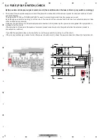
Page 14: ... This product may receive excessive current if the power line connection of the external product is incorrect such as Ground connection failure The poly switch P1243 on TUNER AMP UNIT is used to protect this product from this excessive current Even though poly switch is working to cut the circuit the sounds of Pre out output and AUX input are output properly and also other functions work correctly...

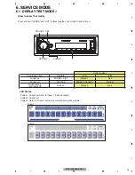
Page 15: ...ONE LIST States 1 Red All light off SOURCE States 2 No light No light Button feeling and ILM light Button 3 States 3 Blue LCD States Status 1 All light up Refer to Draw 1 below for detail States 2 All light off Status 3 Refer to Draw 2 below for deference among the models Draw 1 Draw 2 Press and hold PHONE and LIST buttons together and turn BUP and ACC on How to enter Test mode ...

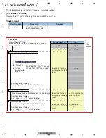
Page 16: ...ormed as usual in appearance The screen gets still when entering this item On an initial value On lighting condition of normal times On an initial value or setting value of default menu On an initial value or setting value of default menu On an initial value or setting value of default menu Off All off All off All off Remarks Key Illumination Operation key Processing Icon Enter display test mode S...

Page 17: ...xtension scd 3 Enter INITIAL SETTING MENU select S W UPDATE and push ENTER key Wait CHECK FILE state 4 The unit checks upgrade data file and starts updating automatically 5 Wait until the end of updating Alternately displaying DO NOT and POWER OFF 5 second intervals 6 If update is completed displaying COMPLETED and restarting automatically Layers First Layer Second Layer Third Layer Fourth Layer D...

Page 18: ...ve the Tuner Amp Assy 1 1 Heat Sink side The Chassis side is made a bottom Removing the Tuner Amp Assy Fig 2 Chassis Tuner Amp Assy Release the two latches Release the two latches and then remove the Panel Assy Removing the Panel Assy Fig 1 Fig 2 Fig 1 Remove the screw Remove the two screws Panel Assy 4 3 3 Fig 3 Removing the Tuner Amp Unit Fig 3 1 Remove the two screws and then remove the Tuner A...

Page 19: ... side hook of the button at the same time and pull out the button 1 Remove the arm while bending the rib of the panel upward Assembling the Panel Part Fig 6 7 8 1 Attach the button from the front side of the panel 2 Attach the spring to the arm as shown in the figure Hitch the spring to the groove The bended tip of the spring is set to this side ...

Page 20: ...mation to be shown in this chapter Fig 8 3 Fit the spring in the groove at the position shown in the figure 4 Fit the boss on the lower side of the arm in the lower hole of the panel and then warp the rib on the panel in the direction shown in the figure and fit the boss of the arm in the panel ...

Page 21: ... sure to use parts of identical designation Screw adjacent to mark on the product are used for disassembly For the applying amount of lubricants or glue follow the instructions in this manual In the case of no amount instructions apply as you think it appropriate X580BS XNUC X580BS XNUC X585BT XNES X580BT XNEW5 X580DAB XNEW5 X580DAB XNEW5 X580DAB XNEW5 X580BT XNEW5 X580BT XNEW5 X585BT XNES A A X58...

Page 22: ... Contrast table 2 17 Screw See Contrast table 2 Mark No Description Part No Mark No Description MVH X580BS XNUC MVH X580DAB XNEW5 MVH X580BT XNEW5 MVH X585BT XNES 1 Unit Box QHG4018 QHG3883 QHG3884 QHG3887 2 Contain Box QHL4018 QHL3883 QHL3884 QHL3887 4 Polyethylene Bag CEG1173 QEG3001 QEG3001 QEG3001 5 Card Remote Control Unit QXE1044 Not used Not used QXE1044 6 1 Warranty Card QRY3001 CRY1376 CR...

Page 23: ...580BS XNUC 23 5 6 7 8 5 6 7 8 C D F A B E 9 2 EXTERIOR A A A X580BT XNUC X585BT XNES X580DAB XNEW5 X580BT XNEW5 X580BS XNUC X585BT XNES X580DAB XNEW5 C D X585BT XNES X580DAB XNEW5 C X585BT XNES A E A E D A B ...

Page 24: ...le 2 41 Screw BPZ26P080FTC 42 Heat Sink See Contrast table 2 43 Screw BSZ26P120FTC 44 Fuse 10 A YEK5001 45 Screw BSZ26P120FTC 46 Screw ASZ26P050FTC 47 48 Screw BSZ26P060FTC 49 Gasket QNM3174 50 WWR Tuner Unit U951 See Contrast table 2 51 Holder See Contrast table 2 52 Cover See Contrast table 2 53 Card Remote Control Unit See Contrast table 2 54 55 Cord Assy See Contrast table 2 56 Lighting Conduc...

Page 25: ...QXE1044 55 Cord Assy CDP1484 QDP3072 QDP3072 CDP1484 62 Keyboard Unit QWM4243 QWM4242 QWM4242 QWM4243 65 ANT Pigtail Cable Assy Not used QXA4122 Not used Not used 67 USB Cable Not used Not used Not used QDP3089 68 Screw Not used Not used Not used BSZ26P060FTC Mark No Description MVH X580BS XNUC MVH X580DAB XNEW5 MVH X580BT XNEW5 MVH X585BT XNES ...

Page 26: ...107 1000p 50 C110 1000p 50 C109 1000p 50 ILL GND ACC BREM TEL RR RL RR RL FR FL FR FL B UP B UP B UP TEL MUTE ILL SENS ASENS D Ref 111 120 Ref 121 130 Ref 131 140 TUNER AMP UNIT VEHICLE I F 13 13 A 10 SCHEMATIC DIAGRAM Note When ordering service parts be sure to refer to EXPLODED VIEWS AND PARTS LIST or ELECTRICAL PARTS LIST 1 13 A 5 13 A POWER SUPPLY SPEAKER Symbol indicates a resistor No differe...

Page 27: ... NC1 6 HSW 7 GND4 8 SW2 9 FB2 10 INV2 11 VOUT0 12 VIN1 13 ADJ1 14 VOUT1 15 ADJ2 16 VOUT2 17 GND3 18 NC2 19 VIN2 20 SNSH 21 SNSL 22 GATE1 23 FB1 24 INV1 25 VOUT4 26 ADJ4 27 VOCAL 28 CLCAL 29 VIN4 30 VIN3 31 ADJ3 32 VOUT3 33 GND2 34 RT 35 GND1 36 SYNC 37 SCL 38 SDA 39 REG4OCB 40 BSENS 41 ECO 42 REG4EN 43 EN 44 ADJ5 45 EP C245 0 1u 16 1608 GND GND GND GND R256 0 GND GND R257 NM C246 NM C248 CCG1393 C...

Page 28: ...305 6 8k R304 43k R306 0 USB_CTL1 BUP14 4V IC321 BD2232G G VIN 1 GND 2 EN 3 OC 4 5 VOUT C321 1u 10 1608 C323 NM C324 1u 10 1608 USB1_5V GND GND C309 3216 CCG1236 10u 35V C311 CCG1396 A 1608 50V 1u C322 1u 10 1608 R321 2 2k R322 0 D302 RB060M 30 R303 180k C313 1000p 50 1608 GND GNDR307 NM GND GND C314 NM C308 0 01u 50 1608 NM C325 C316 NM 1608 C315 0 1u 16 1608 GND GND GND GND C326 NM 2125 GND C317...

Page 29: ...OUT_EN C462 CCG1192 10u 10V 2125 C461 NM C448 NM C446 NM VDDIO_ON3 3V 2SAR502UB Q441 R442 220 1608 R441 10k R443 NM Q442 LTC023YEB R484 NM GND C482 1u 10 2SAR502UB Q481 47u 6 3 C481 R482 10k VDDIO_ON3 3V R483 NM LTC043EEB Q482 R481 470 OPAL_3 3V C464 3216 CCG1236 10u 35V C442 CCG1192 10u 10V 2125 C432 CCG1192 10u 10V 2125 C430 CCG1192 10u 10V 2125 C428 CCG1192 10u 10V 2125 C426 CCG1192 10u 10V 212...

Page 30: ...MMC0_DATA_3 R18 SDMMC0_CLK R19 GPIO39 T1 JTAG_TDI T2 JTAG_TDO T3 JTAG_TCK T4 JTAG_TMS T5 NC24 T6 NC25 T7 NC26 T8 NC27 T9 NC28 T10 NC29 T11 NC30 T12 NC31 T13 NC32 T14 NC33 T15 NC34 T16 GPIO37 T17 GPIO36 T18 GPIO38 T19 GPIO70 U1 GPIO76 U2 JTAG_TRSTn U3 NC35 U4 NC36 U5 NC37 U6 NC38 U7 NC39 U8 NC40 U9 NC41 U10 NC42 U11 NC43 U12 NC44 U13 NC45 U14 NC46 U15 NC47 U16 NC48 U17 NC49 U18 GPIO68 U19 GPIO69 V1...

Page 31: ... 7k R705 2 2k LSAR523UB Q701 R709 47k GND C702 0 1u 10 R704 100 R708 2 7k R703 100 R702 4 7k GND MX25L1636EM2I 08G IC742 CS 1 SO SIO1 2 WP SIO2 3 GND 4 5 SI SIO0 6 SCLK 7 NC SIO3 8 VCC GND GND L741 NM R747 33 R748 33 R745 33 R744 33 C742 0 1u 10 C743 0 1u 10 C731 0 1u 10 R711 0 R741 33 SD_DA14 SD_DA11 SD_DA13 SD_DA10 SD_DA12 SD_DA7 SD_CKE SD_DQM0 SD_CLK SD_DQM1 SD_DA9 SD_DA1 SD_DA8 SD_CS SD_DA0 SD...

Page 32: ...802 3216 CCG1255 C809 3216 CCG1255 C804 2125 CCG1325 C760 1u 10 1608 C805 2125 CCG1325 C806 2125 CCG1325 47u 6 3 C768 C807 2125 CCG1325 C808 2125 CCG1325 47u 6 3 C762 C813 3216 CCG1255 47u 6 3 C767 C770 NM C774 10p 50 D801 NM HIOUT8V AUXGND IC751 PM9015A INAP2L 1 INBN3L 2 INBP4L 3 INCN5L 4 INCP6L 5 INDN7L 6 INDP8L 7 INMPN 8 INMN 9 INDP8R 10 INDN7R 11 INCP6R 12 INCN5R 13 INBP4R 14 INBN3R 15 INAP2R ...

Page 33: ...55 NM R880 NM R869 0 R859 NM R876 R870 100 R875 4 7k R871 1k R883 1k R884 120 TUN3 3V TUN_SCL TUNAD1 TUN_SDA TUN_BBD2 TUN_BBCLK TUN_BBWS Tuner_R Tuner_AG TUNAWS TUNAD2 TUNACLK TUN_BBD1 Tuner_L C874 39p 50 C851 NM P852 IMSA 6803 01Y900 P851 NM L851 NM R877 R878 R879 C857 NM 2125 X851 CSS1868 A TUNDATA TUNACLK1 TUNAWS1 R885 NM R886 NM C852 NM C885 0 1u 10 L857 T851 CTC1215 A 1 2 3 4 5 L862 NM L861 N...

Page 34: ...K DTUNTOSYS TUNAD1 DABSXI14V U951 CWE2534 1 2 DABANT 3 4 5 6 7 8 9 10 11 12 13 14 15 16 17 GPIO 18 TX 19 RX 20 RESET 21 22 23 SCS 24 SSCK 25 SDO 26 SDI 27 28 29 30 31 32 BB_DII 33 BB_WS 34 BB_CLK 35 36 37 38 A_DO 39 A_DI 40 A_WS 41 A_CLK R952 R953 R954 R955 R958 100 R957 100 R959 100 R960 100 C963 NM 1608 GND GND R964 NM R965 NM R966 0 1608 GND GND R967 NM 1608 GND GND R968 0 1608 GND GND C964 NM ...

Page 35: ...TWAKE 1 NC1 2 VBAT 3 BTWAKE 4 LPO_IN 5 GND1 6 I2S_WS 7 I2S_CLK 8 I2S_DI 9 I2S_DO 10 VIO 11 REG_ON 12 NC2 13 GND2 14 UART_TXD 15 UART_RXD 16 UART_RTS 17 UART_CTS 18 CLK_REQ 19 GND3 20 GND4 22 GND5 23 GND6 24 GND7 25 GND8 26 R1006 0 R1007 0 C1001 NM C1002 NM C1003 0 1u 16 1608 C1004 0 1u 16 1608 GND R1008 0 1608 GND GND R1009 NM R1010 NM R1011 0 R1012 220 R1013 0 R1014 0 1608 GND GND R1015 0 1608 GN...

Page 36: ...0 C1101 0 01u 16 DGND1 C1105 1u 10 CDDATAIN CD_RST CD_SDA CDSCKIN CDLRCKIN CD_STBY CDSKIP CDWAIT CDSRQ CD_SCL VD6V R1115 4 7k R1116 4 7k R1117 4 7k R1118 4 7k VDDIO3 3V R1120 150 R1121 150 R1122 150 VDDIO_ON3 3V R1123 0 R1124 NM L1102 VTL1133 A L1103 VTL1133 A L1104 VTL1133 A C1107 0 1u 16 1608 GND R1126 0 R1127 NM R1119 NM R1102 47k R1103 47k R1111 47k C1108 0 1u 16 1608 GND D1102 DZ2S068C D1101 ...

Page 37: ...E2 4 5 B2 6 C1 R1223 10k R1222 1 5k D1221 DZ2J039M0 HIOUT8V R1221 1 2k GND AEQMICIN MICSENS LCDTOSYS SYSTOLCD LCD_SCE LCD_SCK C1221 0 1u 10 BT_MICN BT_MICP AEQAUXSW R1214 2 2k 1608 R1215 100 1608 R1207 220 1608 R1208 0 1608 P1243 FSMD075 1 2 USB2_5V CN1291 KM200NA5L 1 2 3 4 5 NM KN1 1 NM KN2 1 GND GND GND ILMPW C1242 CCG1192 2125 10u 10V C1243 CCG1192 2125 10u 10V C1245 CCG1192 2125 10u 10V C1246 ...

Page 38: ... GND R1311 NM R1312 NM 1608 GND GND R1313 0 1608 R1314 0 1608 GND GND R1316 NM 1608 C1328 1u 10 1608 C1329 NM 2125 GND AMP D D A A A A A A A A A A A A TUNER AMP UNIT POWER AMP 13 13 A 12 13 A 7 13 A 5 13 A No connection PA2032A PAL013B The pin number of left side is a number on the PCB silk printing The pin number of right side in the IC frame means the pin number of IC itself 1 13 A 12 13 A 7 13 ...

Page 39: ...SCR523UB S1821 CSG1155 1 2 3 4 C1841 NM C1850 NM S1823 CSG1155 1 2 3 4 C1844 NM R1848 NM R1822 NM C1847 NM Q1842 LSCR523UB S1825 CSG1155 1 2 3 4 C1842 NM Q1847 LSCR523UB C1843 NM Q1849 LSCR523UB DGND Q1848 LSCR523UB ILMGND R1850 NM R1852 NM C1857 NM R1876 NM C1856 NM R1872 NM NM D1846 1 2 3 4 5 6 R1874 NM C1858 NM C1854 NM ILMGND SMLVN6RGB2UK B D1844 1 2 3 4 5 6 DGND DGND SMLVN6RGB2UK B D1845 1 2 ...

Page 40: ...1 R1005 C1221 R122 P1243 R123 R701 1 5 Q1221 D1201 R702 E Q1222 R703 1 5 Q1223 R704 D1204 R511 L751 R705 D1205 L752 R706 D1206 R707 D1207 R1203 R514 R708 R1204 D1208 R709 R515 R516 R1206 R323 R517 R1207 R518 R1208 R519 R131 C1231 R1209 R132 C1232 R133 R710 R711 1 5 IC461 15 20 10 1 5 CN501 L951 L952 R712 1 5 CN502 L953 R713 R520 1 R714 1 R715 1 R716 R522 1 R717 R523 R524 1 R718 1 R719 25 30 20 15 ...

Page 41: ...C1215 C1217 C1218 R1006 R1007 R1008 R1009 D1202 D1203 R510 R1201 R512 R513 R1010 R321 R1205 D1209 R1011 R322 R1012 R1013 R1014 R1015 R1016 R1017 D1210 R1018 D1211 R1210 R1211 R1212 R1213 R1214 R525 R1215 R526 R1216 R1217 C103 C104 R1219 C105 C106 C107 C108 C109 R726 R727 R728 C110 R729 R535 VA1276 VA1277 C1255 C1256 P1276 C1257 C504 R541 C505 C506 C507 R544 C508 C509 R546 R548 C510 C511 R741 C512 ...

Page 42: ...1921 R1921 R1922 C1951 C1952 C1953 R1933 R1941 R1942 R1943 R1944 R1951 R1952 R1953 R1954 C1801 C1802 R1801 R1802 R1803 R1804 R1805 1 5 1 0 1 5 2 0 2 5 3 0 3 5 4 0 4 5 5 0 5 5 6 0 6 5 7 0 7 5 8 0 IC1801 1 5 1 0 1 5 2 0 2 5 3 0 3 5 4 0 4 5 5 0 5 5 6 0 6 5 7 0 7 5 8 0 IC1802 C1841 C1842 C1843 C1844 E Q1841 C1845 E Q1842 C1846 E Q1843 C1847 E Q1844 C1848 E Q1845 R1821 C1849 E Q1846 R1822 E Q1847 E Q18...

Page 43: ...4184DL3 08A IC501 Microprocessor IC STA1080 IC 502 IC S 80827CNMC B8M IC 503 L MOS And Gate A TC7SET08FUS1 IC 504 IC A TC7SH126FU IC 701 IC 337S3959 IC 702 RAM IC M12L128168A 5TG2N IC 731 ROM IC M95512 RMN6P IC 741 IC A QWW4081 IC 741 IC B QWW4082 IC 741 IC C D QWW4078 IC 742 IC MX25L1636EM2I 08G IC 751 E VOL System LSI PM9015A IC 801 Op amp IC D NJW1240V IC 851 Tuner IC TEF6686HN V102 IC 1301 Pow...

Page 44: ... VTL1126 L 1296 Chip Beads VTL1126 L 1297 Chip Beads VTL1126 T 851 Variable Coil CTC1215 X 501 Resonator 24 MHz CSS1773 X 502 Resonator 32 768 kHz CSS1807 X 751 Crystal Resonator 18 432MHz CSS1826 X 851 Crystal Resonator CSS1868 S 501 Switch RESET CSG1020 Circuit Symbol and No Part No P 401 Poly Switch A FSMD110 24R P 401 Poly Switch B FSMD020 R P 852 Surge Absorber IMSA 6803 01Y900 P 1243 Poly Sw...

Page 45: ...17 RS1 16SS221J R 518 RS1 16SS472J R 519 RS1 16SS271J R 520 B RS1 16SS472J R 522 RS1 16SS0R0J R 524 RS1 16SS3001D Circuit Symbol and No Part No R 525 RS1 16SS103J R 526 RS1 16SS1213F R 527 D RS1 16SS0R0J R 528 D RS1 16SS0R0J R 529 RS1 16SS0R0J R 530 RS1 16SS0R0J R 531 RS1 16SS222J R 532 RS1 16SS102J R 533 RS1 10SR103J R 534 RS1 10SR103J R 536 D RS1 16SS473J R 537 A B C RS1 16SS473J R 538 C RS1 16S...

Page 46: ...1 10SR0R0J R 731 RS1 16SS330J R 732 RS1 16SS330J R 733 RS1 16SS103J Circuit Symbol and No Part No R 734 RS1 16SS103J R 735 RS1 16SS103J R 736 RS1 16SS330J R 737 RS1 16SS330J R 741 RS1 16SS330J R 742 RS1 16SS103J R 743 RS1 16SS103J R 744 RS1 16SS330J R 745 RS1 16SS330J R 746 RS1 16SS103J R 747 RS1 16SS330J R 748 RS1 16SS330J R 749 RS1 16SS330J R 750 RS1 16SS103J R 753 RS1 16SS0R0J R 754 RS1 16SS105...

Page 47: ...0 RS1 16SS223J R 1251 RS1 16SS223J R 1252 RS1 16SS223J R 1253 RS1 16SS0R0J R 1255 RS1 16SS0R0J R 1257 A B C RS1 16SS0R0J R 1258 A B C RS1 16SS0R0J Circuit Symbol and No Part No R 1259 A B C RS1 16SS0R0J R 1260 A B C RS1 16SS0R0J R 1261 A B C RS1 16SS0R0J R 1262 A B C RS1 16SS0R0J R 1263 RS1 10SR0R0J R 1277 D RS1 16SS471J R 1278 RS1 16SS102J R 1279 D RS1 16SS471J R 1280 RS1 16SS102J R 1281 RS1 16SS...

Page 48: ...246 C 442 10 uF CCG1192 C 444 10 uF CCG1192 C 462 10 uF D CCG1192 C 464 10 uF D CCG1236 C 481 CEVQW470M6R3 C 482 1 uF DCH1246 Circuit Symbol and No Part No C 502 CKSSYB104K10 C 503 4 7 uF CCG1212 C 505 CKSSYB104K10 C 506 4 7 uF CCG1212 C 507 4 7 uF CCG1212 C 508 CKSSYB104K10 C 509 4 7 uF CCG1212 C 510 CKSSYB104K10 C 511 4 7 uF CCG1212 C 512 CKSSYB104K10 C 513 4 7 uF CCG1212 C 514 CKSSYB104K10 C 51...

Page 49: ...1325 C 805 1 uF D CCG1325 C 806 1 uF D CCG1325 C 807 1 uF D CCG1325 Circuit Symbol and No Part No C 808 1 uF D CCG1325 C 809 1 uF D CCG1255 C 810 1 uF D CCG1255 C 811 D CKSQYB104K50 C 813 1 uF D CCG1255 C 814 1 uF D CCG1255 C 853 CCSSCH100D50 C 854 CCSSCH471J50 C 858 CCSSCH220J50 C 859 CCSSCH331J50 C 860 D CCSSCK2R0C50 C 861 D CCSSCK1R0C50 C 862 D CCSSCK1R0C50 C 863 D CCSSCH120J50 C 866 CKSSYB224K...

Page 50: ...VN6RGB2UK B D 1844 LED SMLVN6RGB2UK B D 1845 LED SMLVN6RGB2UK B D 1901 SMD Varistor MLV0402ES012V0010N Circuit Symbol and No Part No D 1902 SMD Varistor MLV0402ES012V0010N L 1901 Inductor CTF1713 L 1921 Inductor CTF1786 L 1922 Inductor CTF1786 L 1923 Inductor CTF1786 S 1821 Push Switch CSG1155 S 1823 Push Switch CSG1155 S 1825 Push Switch CSG1155 S 1826 Push Switch CSG1155 S 1827 Push Switch CSG11...

Page 51: ...SR222J R 1952 B C RS1 16SS473J R 1953 A D RS1 10SR101J CAPACITORS C 1801 CKSRYB105K10 C 1802 CKSRYB105K10 C 1901 CKSRYB105K10 C 1902 CKSRYB104K16 C 1904 CKSRYB105K16 C 1905 CKSRYB105K16 C 1906 4 7 uF CCG1212 C 1951 10 uF A D CCG1192 C 1952 CCSSCH470J50 C 1953 CCSSCH470J50 Circuit Symbol and No Part No ...

Reviews: