Connecting the Units
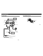
Connection Diagram
Fig. 1
Head Unit
(sold separately)
IP-BUS cable
To IP-BUS Input
(Blue)
Yellow
To terminal always supplied with power
regardless of ignition switch position.
Black (ground)
To vehicle (metal) body.
Fuse holder
IP-BUS Output
(Black)
This Unit
Antenna Input
Power Supply
Antenna Unit
(AN-91XM)
(sold separately)
IP-BUS Input
(Blue)
Multi-CD player
(sold separately)
Green
(Terrestrial)
Yellow (Satellite)
Black
6 m
(19 ft. 8 in.)
Protect the Antenna Connector
Fig. 2
Screw (3
×
6 mm)
Summary of Contents for GEX-P910XM
Page 4: ......

