5
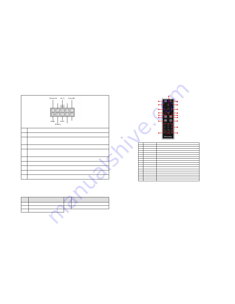
Power Input/Output Port
1
Power GND (Black wire). To vehicle (metal) body.
2
Reserved
3
+12V Input (Yellow wire). To terminal supplied with power
regardless of ignition switch position.
4
Reserved
5
ACC In (Red wire). To electric terminal controlled by ignition
switch On/Off.
6
IR LED. Power for the LED of the IR receiver.
7
Reserved
8
IR data In. Infrared data input of the IR receiver.
9
IR Power Out. Power for IR LED.
10 IR GND. Ground for IR LED.
Accessories
The table below lists all accessories supplied in the package.
No.
Part Name
No.
Part Name
1
Power with IR Cord
4
Pioneer RGB Cable
2
IR Extension Cable
5
2 Active Rod Antennas
3
Remote Controller
Remote Control Operations
Remote Control Battery Installation
Before attempting to operate your remote control, install the battery as
described below:
1.
Open the battery cover at the back side of the remote control.
2.
Take out the battery and put another battery in.
3.
Put the cover back.
Button name
Function
1
POWER
Select power-on or stand-by
2
MUTE
Mute control
3
Home
Go to home screen
4
EXIT
Exit the current setup
5
EPG
Electronic Program Guide
6
MENU
Enter the setup menu
7
Cursor
Move the cursor right
8
Cursor
Move the cursor left
9
OK
Select the highlighted item
10
CH▲
Select channel up or move the cursor up
11
CH▼
Select channel down or move the cursor down
12
PLAY/PAUSE
Select play or pause
13
FF
Fast Forward
14
REC
●
Start record TV/Radio program or exit recording
15
FR
Fast Rewind
16
Digital keys
Digit buttons to select channels
17
INFO
Display digital TV system information
18
AUTO SCAN
To scan channels automatically
NULL
NULL
NULL
+12V In
(1)
(5)
(8)
(6)
––
)
(9)
(14)
(15)
(18)
(10)
(2)
(3)
(7)
(11)
(4)
(12)
(13)
(16)
(17)
NULL


