background image

Connecting your equipment

15

En

02

02

Connecting a TV and playback components

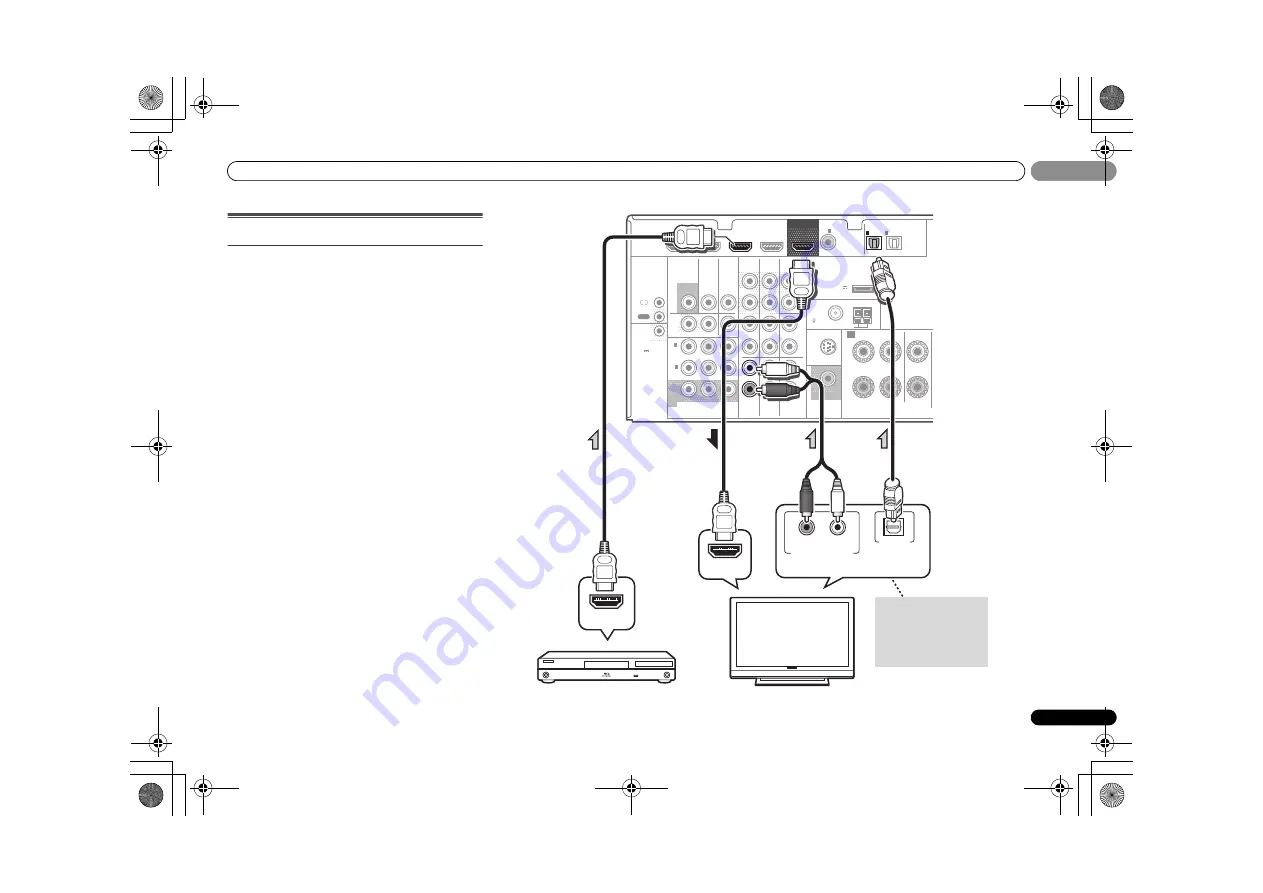
Connecting using HDMI

If you have an HDMI or DVI (with HDCP) equipped 
component (Blu-ray Disc player, etc.), you can connect it to 
this receiver using a commercially available HDMI cable.
If the TV and playback components support the 

Control

 with 

HDMI feature, the convenient 

Control

 with HDMI functions 

can be used (see 

Control with HDMI function

 on page 43).

• The following connection/setting is required to listen to 

the sound of the TV over this receiver.
-

If the TV does not support the HDMI Audio Return 
Channel function, connect the receiver and TV with 
audio cables (as shown).

-

If the TV supports the HDMI Audio Return Channel 
function, the sound of the TV is input to the receiver via 
the HDMI terminal, so there is no need to connect an 
audio cable. In this case, set 

ARC

 at 

HDMI Setup

 to 

ON


(see 

HDMI Setup

 on page 43).

MONITOR

OUT

ZONE2

HDMI

VIDEO

COMPONENT  VIDEO

DVR/
BDR

L

R

R

L

Y

P

B

P

R

AUDIO

ANTENNA

OPTICAL

ASSIGNABLE

ASSIGN
ABLE

ASSIGNABLE

OUT

A

DVR/BDR

OUT

CD-R/TAPE

COAXIAL

IN

(

CD

)

1

PRE OUT

SUBWOOFER

IN

IN

L

R

OUT

CD

MONITOR

OUT

TV/SAT

IN

BD

IN

OUT

IN

DVD IN

IN

TV/SAT

BD

IN

DVD

(

DVD

)

IN

1

MONITOR

OUT

(

DVR/

BDR

)

IN

2

DVR/BDR IN

DVD IN

BD IN

VIDEO 1 IN

(

TV/SAT

)

IN

1

(

CD-R/TAPE

)

IN

2

FM UNBAL

75

(

OUTPUT 5 V

  0.1 A MAX

)

ADAPTER PORT

AM LOOP

IN

SIRIUS

FRONT

R

L

CENTER

12 V 

TRIGGER

(OUTPUT
 12 V

50 mA
MAX)

IR

IN

OUT

HDMI IN

HDMI OUT

R

L

DIGITAL AUDIO OUT

ANALOG AUDIO OUT

OPTICAL

Select one

HDMI/DVI-compatible TV

HDMI/DVI-compatible 

Blu-ray Disc player

If the TV does not support 
the HDMI Audio Return 
Channel function, this 
connection is required to 
listen to the TV sound over 
the receiver.

VSX-40_UCSMXCN_En.book  15 ページ  2011年3月4日 金曜日 午前10時27分

Summary of Contents for Elite VSX-40

Page 1: ...nce claim such as loss or theft Improve product development Your input helps us continue to design products that meet your needs Receive a free Pioneer newsletter Registered customers can opt in to receive a monthly newsletter Receive free tips updates and service bulletins on your new product AUDIO VIDEO MULTI CHANNEL RECEIVER VSX 40 Operating Instructions VSX 40_UCSMXCN_En book 1 ページ 2011年3月4日 金...

Page 2: ... 1 2_A1_En Information to User Alterations or modifications carried out without appropriate authorization may invalidate the user s right to operate the equipment D8 10 2_A1_En WARNING This equipment is not waterproof To prevent a fire or shock hazard do not place any container filled with liquid near this equipment such as a vase or flower pot or expose it to dripping splashing rain or moisture D...

Page 3: ...nit should be performed only by qualified service personnel If connected to an AC outlet the cut off plug can cause severe electrical shock Make sure it is properly disposed of after removal The equipment should be disconnected by removing the mains plug from the wall socket when left unused for a long period of time for example when on vacation D3 4 2 2 1a_A1_En CAUTION The STANDBY ON switch on t...

Page 4: ... of Music 29 Wireless music play 29 Pairing the Bluetooth ADAPTER and Bluetooth wireless technology device 30 Listening to Music Contents of Bluetooth wireless technology device with Your System 30 Listening to Satellite Radio 30 Listening to SIRIUS Radio 31 Saving channel presets 31 Using the SIRIUS Menu 31 Listening to the radio 32 Improving FM sound 32 Saving station presets 32 Listening to sta...

Page 5: ...er terminal page 12 2 Connecting the components For surround sound you ll want to hook up using a digital connection from the Blu ray Disc DVD player to the receiver About the video converter page 14 Connecting a TV and playback components page 15 Connecting antennas page 20 Plugging in the receiver page 23 3 Power On Make sure you ve set the video input on your TV to this receiver Check the manua...

Page 6: ... stations for recall page 32 Used to preset the channel in SIRIUS Radio page 31 TUNE Used to find radio frequencies page 32 and SIRIUS Radio channels page 31 PRESET Use to select preset radio stations page 32 and to select SIRIUS Radio channels page 31 7 Remote sensor Receives the signals from the remote control see Operating range of remote control on page 9 8 MASTER VOLUME dial 9 STANDBY ON 10 P...

Page 7: ... is active page 45 21 Sleep timer indicator Lights when the receiver is in sleep mode page 8 22 PRESET information or input signal indicator Shows the preset number of the tuner or the input signal type etc 23 Character display Displays various system information 24 DTS indicators DTS Lights when a source with DTS encoded audio signals is detected HD Lights when a source with DTS EXPRESS or DTS HD...

Page 8: ...u ray Disc DVD HOME MENU Displays the HOME MENU screen RETURN Confirm and exit the current menu screen MENU Displays the TOOLS menu of Blu ray Disc player Press TUNER or SIRIUS first to access TUNER EDIT Memorizes stations for recall page 32 When TUNER is pressed also used to change the name page 32 BAND Switches between AM FM ST stereo and FM MONO radio bands page 32 CATEGORY Press to browse SIRI...

Page 9: ... the TV input signal CH Use to select channels VOL Use to adjust the volume on your TV 13 MASTER VOLUME Use to set the listening volume 14 MUTE Mutes unmutes the sound 15 DISP Switches the display of this unit The listening mode sound volume Speaker System setting or input name can be checked by selecting an input source The Speaker System setting may or may not be displayed depending on the input...

Page 10: ...bove connections are performed Select Surr Back if the surround back speaker or speaker B is connected and Height if the front height speaker is connected see The Speaker System setting on page 41 ZONE 2 connection Multi Zone With these connections you can simultaneously enjoy the surround sound in the main zone with stereo playback on another component in ZONE 2 The selection of input devices is ...

Page 11: ...from your CRT TV The subwoofer can be placed on the floor Ideally the other speakers should be at about ear level when you re listening to them Putting the speakers on the floor except the subwoofer or mounting them very high on a wall is not recommended When not connecting a subwoofer connect speakers with low frequency reproduction capabilities to the front channel The subwoofer s low frequency ...

Page 12: ...ake sure that all the bare speaker wire is twisted together and inserted fully into the speaker terminal If any of the bare speaker wire touches the back panel it may cause the power to cut off as a safety measure Switching the speaker terminal If you selected Surr Back in The Speaker System setting on page 41 you can switch between speakers using the SPEAKERS button If you selected Height the but...

Page 13: ...al transfer of uncompressed video contents protected by HDCP 1080p 24 1080p 60 etc 3D signal transfer Deep Color signal transfer x v Color signal transfer Audio Return Channel Input of multi channel linear PCM digital audio signals 192 kHz or less for up to 8 channels Input of the following digital audio formats Dolby Digital Dolby Digital Plus DTS High bitrate audio Dolby TrueHD DTS HD Master Aud...

Page 14: ...monitor TV to the receiver s HDMI video outputs when connecting this video source Note If several video components are assigned to the same input function the converter gives priority to HDMI component then composite in that order If the video signal does not appear on your TV try adjusting the resolution settings on your component or display Note that some components such as video game units have...

Page 15: ... via the HDMI terminal so there is no need to connect an audio cable In this case set ARC at HDMI Setup to ON see HDMI Setup on page 43 MONITOR OUT ZONE2 HDMI VIDEO COMPONENT VIDEO DVR BDR L R R L Y PB PR AUDIO ANTENNA OPTICAL ASSIGNABLE ASSIGN ABLE ASSIGNABLE OUT A DVR BDR OUT CD R TAPE COAXIAL IN CD 1 PRE OUT SUBWOOFER IN IN L R OUT CD MONITOR OUT TV SAT IN BD IN OUT IN DVD IN IN TV SAT BD IN DV...

Page 16: ... more on this Note In order to listen to the audio from the DVD player that is connected to this receiver using an optical cable or a coaxial cable first switch to the DVD input then use and SIGNAL SEL to choose the audio signal O2 OPTICAL2 or C1 COAXIAL1 see Selecting the audio input signal on page 26 RECEIVER ZONE2 HDMI VIDEO COMPONENT VIDEO DVR BDR L R R L Y PB PR AUDIO ANTENNA OPTICAL ASSIGNAB...

Page 17: ...hat is connected to this receiver using an optical cable or a coaxial cable first switch to the DVD input then use and SIGNAL SEL to choose the audio signal O2 OPTICAL2 or C1 COAXIAL1 see Selecting the audio input signal on page 26 RECEIVER HDMI OUT ZONE2 HDMI VIDEO COMPONENT VIDEO DVR BDR L R R L Y PB PR AUDIO ANTENNA OPTICAL ASSIGNABLE ASSIGN ABLE ASSIGNABLE OUT A DVR BDR OUT CD R TAPE COAXIAL I...

Page 18: ...sing an optical cable first switch to the DVR BDR input then use and SIGNAL SEL to choose the audio signal O2 OPTICAL2 see Selecting the audio input signal on page 26 ZONE2 HDMI VIDEO COMPONENT VIDEO DVR BDR L R R L Y PB PR AUDIO ANTENNA OPTICAL ASSIGNABLE ASSIGN ABLE ASSIGNABLE OUT A DVR BDR OUT CD R TAPE COAXIAL IN CD 1 PRE OUT SUBWOOFER IN IN L R OUT CD MONITOR OUT TV SAT IN BD IN OUT IN DVD IN...

Page 19: ... analog audio jacks if you want to record to from digital components like an MD to from analog components Note In order to listen to the audio from the CD player that is connected to this receiver using a coaxial cable first switch to the CD R input then use and SIGNAL SEL to choose the audio signal C1 COAXIAL1 see Selecting the audio input signal on page 26 ZONE2 VIDEO COMPONENT VIDEO DVR BDR L R...

Page 20: ...enna wires 2 Fix the AM loop antenna to the attached stand To fix the stand to the antenna bend in the direction indicated by the arrow fig a then clip the loop onto the stand fig b 3 Place the AM antenna on a flat surface and in a direction giving the best reception 4 Connect the FM wire antenna into the FM antenna socket For best results extend the FM antenna fully and fix to a wall or door fram...

Page 21: ...ill allow you to control playback of audio content from your iPod using the controls of this receiver Switch the receiver into standby and then use the iPod cable to connect your iPod to the iPod terminal on the front panel of this receiver Push down on the PUSH OPEN tab to access the iPod terminal For the cable connection refer to also the operating instructions for iPod For instructions on playi...

Page 22: ... and off using the 12 volt trigger You can connect components in your system such as a screen or projector to this receiver so that they switch on or off using 12 volt triggers when you select an input function However you must specify which input functions switch on the trigger using the The 12 V Trigger Setting on page 42 Note that this will only work with components that have a standby mode Con...

Page 23: ...ped on A damaged power cord can cause a fire or give you an electric shock Check the power cord once in a while If you find it damaged ask your nearest Pioneer authorized independent service company for a replacement The receiver should be disconnected by removing the mains plug from the wall socket when not in regular use e g when on vacation Note After this receiver is connected to an AC outlet ...

Page 24: ...reens and select menu items Press RETURN to exit the current menu Press SETUP at any time to exit the System Setup menu If you cancel the Auto MCACC setup at any time the receiver automatically exits and no settings will be made The screensaver automatically starts after three minutes of inactivity 5 Select Auto MCACC from the System Setup menu then press ENTER MIC IN blinks when the microphone is...

Page 25: ... sound from your system but it is also possible to adjust these settings manually using the System Setup menu starting on page 38 Note Depending on the characteristics of your room sometimes identical speakers with cone sizes of around 12 cm 5 inches will end up with different size settings You can correct the setting manually using the Speaker Setting on page 38 The subwoofer distance setting may...

Page 26: ...Digital DTS and 88 2 kHz 96 kHz PCM 2 channel audio and if there is an MPEG audio option set this to convert the MPEG audio to PCM Depending on your DVD player or source discs you may only get digital 2 channel stereo and analog sound In this case the receiver must be set to a multichannel listening mode if you want multichannel surround sound 5 Use MASTER VOLUME to adjust the volume level Turn do...

Page 27: ...pport ios na Installing software versions other than indicated on the website of Pioneer to your iPod iPhone iPad may result in incompatibility with this receiver iPod and iPhone are licensed for reproduction of non copyrighted materials or materials the user is legally permitted to reproduce Features such as the equalizer cannot be controlled using this receiver and we recommend switching the equ...

Page 28: ...tching iPod videos or browsing photos 2 Press iPod CTRL again to switch back to the receiver controls when you re done Tip Change the receiver s input to the iPod in one action by pressing iPod iPhone iPad DIRECT CONTROL on the front panel to enable iPod operations on the iPod Playing a USB device It is possible to listen to two channel audio using the USB interface on the front of this receiver I...

Page 29: ...application used to encode the AAC file This receiver plays back AAC files encoded by iTunes bearing the extension m4a DRM protected files will not play and files encoded with some versions of iTunes may not play Apple and iTunes are trademarks of Apple Inc registered in the U S and other countries About WMA WMA is an acronym for Windows Media Audio and refers to an audio compression technology de...

Page 30: ... display The system can display alphanumeric characters only Other characters may not be displayed correctly When Bluetooth wireless technology device is not connected NODEVICE appears in the receiver display In this case perform the connection operation from the side of the Bluetooth wireless technology device 6 From the Bluetooth wireless technology device list select Bluetooth ADAPTER and enter...

Page 31: ... the channel In the next 2 seconds the radio broadcast is automatically tuned in To select a channel from your favorite genre press CATEGORY and use to select a genre and then use and ENTER to select a channel from the selected genre Select SR000 SIRIUS ID from the front panel display to check the Radio ID of the SIRIUS Connect tuner To cancel and exit any time press RETURN Tip You can select chan...

Page 32: ...ing and the receiver stores the station Note If the receiver is left disconnected from the AC power outlet for over a month the station memories will be lost and will have to be reprogrammed Stations are stored in stereo When the station is stored in the FM MONO mode it shows as ST when recalled Listening to station presets You will need to have some presets stored to do this See Saving station pr...

Page 33: ...per decoding format will automatically be selected and shows in the display When you select STEREO ALC Auto Level Control stereo mode this unit equalizes playback sound levels if each sound level varies with the music source recorded in a portable audio player When you select STEREO you will hear the source through just the front left and right speakers and possibly your subwoofer depending on you...

Page 34: ...ration EQ ON or OFF The MCACC indicator on the front panel lights when Acoustic Calibration EQ is active You can t use Acoustic Calibration EQ with Stream Direct mode and it has no effect with headphones ACTION Designed for action movies with dynamic soundtracks DRAMA Designed for movies with lots of dialog ENT SHOW Suitable for musical sources ADVANCED GAME Suitable for video games SPORTS Suitabl...

Page 35: ...dergone matrix decoding processing through surround back channel processing to which the Up Mix function is added are output from the surround back speakers Press then press SB CH repeatedly to cycle the surround back channel options Each press cycles through the options as follows SB ON Matrix decoding processing for generating the surround back component from the surround component is turned on ...

Page 36: ... Channel 1 is heard only CH2 Channel 2 is heard only CH1 CH2 Both channels heard from front speakers F PCM Fixed PCM This is useful if you find there is a slight delay before OFF recognizes the PCM signal on a CD for instance When ON is selected noise may be output during playback of non PCM sources Please select another input signal if this is a problem OFF ON DRC Dynamic Range Control Adjusts th...

Page 37: ...nents using the remote control The input source can also be selected by using INPUT SELECT buttons on the remote control or by using the front panel INPUT SELECTOR dial 2 Select the audio input signal if necessary Press then press SIGNAL SEL and select the analog inputs A for the source component of which you want to record see page 26 for more on this 3 Prepare the source you want to record Tune ...

Page 38: ...Sets to automatically turn off the power when the receiver has not operated for several hours see The Auto Power Down menu on page 42 12V Trigger Sets the input function that enables the signal output from the 12 V trigger terminal see The 12 V Trigger Setting on page 42 Manual speaker setup This receiver allows you to make detailed settings to optimize the surround sound performance You only need...

Page 39: ...If you have a subwoofer and like lots of bass it may seem logical to select LARGE for your front speakers and PLUS for the subwoofer This may not however yield the best bass results Depending on the speaker placement of your room you may actually experience a decrease in the amount of bass due to low frequency cancellations In this case try changing the position or direction of speakers If you can...

Page 40: ...MPONENT VIDEO MONITOR OUT or HDMI OUT output down converting component video is not possible after assigning an input If you didn t make component video connections according to the defaults above you must assign the numbered input to the component you ve connected or else you may see the video signal of a different component For more on this see Using the component video jacks on page 19 1 Select...

Page 41: ...press RETURN You return to the Video Parameter menu Resolution Specifies the output resolution of the video signal when video input signals are output at the HDMI OUT terminal select this according to the resolution of your monitor and the images you wish to watch 1 Select Video Parameter from the System Setup menu 2 Select Resolution from the Video Parameter menu 3 Select output resolution AUTO T...

Page 42: ...ished press RETURN You return to the System Setup menu Note Turning the power off using the Auto Power Down will apply to both the main zone and the sub zone However if the Control at HDMI Setup is set to ON the Auto Power Down may not work in the sub zone The 12 V Trigger Setting If the input switches over to the input function set here a control signal is output from the receiver s 12 V trigger ...

Page 43: ...ing all connections connect the power cords to the wall socket After this receiver is connected to an AC outlet a 2 second to 10 second HDMI initialization process begins You cannot carry out any operations during initialization The HDMI indicator on the display unit blinks during initialization and you can turn this receiver on once it has stopped blinking To get the most out of this function we ...

Page 44: ...ches automatically when the Control with HDMI compatible component is played The receiver s input switches automatically when the TV s input is switched The synchronized amp mode remains in effect even if the receiver s input is switched to a component other than one connected by HDMI About connections with a product of a different brand that supports the Control with HDMI function The synchronize...

Page 45: ...ontinues to show in the display 3 Use the INPUT SELECTOR dial to select the source for the zone you have selected For example Z2 CDR sends the source connected to the CDR inputs to the sub room ZONE 2 If you select TUNER you can use the tuner controls to select a preset station see Saving station presets on page 32 if you re unsure how to do this The tuner cannot be tuned to more than one station ...

Page 46: ...codes to TV CONTROL press INPUT here 3 Use the number buttons to enter the preset code You can find the preset codes on page 47 If the correct code has been input the power of the component being input will turn on or off The power of the component being input will only turn on or off if that component is able to be turned on directly by remote control 4 Repeat steps 2 through 3 to try a different...

Page 47: ...t the TV volume SOURCE Press to switch the component assigned to the TV button on or off DTV TV Switches between the DTV and analog TV input modes for Pioneer TVs HOME MENU Use as the GUIDE button for navigating RETURN Use to select closed captioning with DTV Number buttons Use to select a specific TV channel ENTER Use to enter a channel MENU Press to display the DTV menu Select the menu screen EN...

Page 48: ...03 SSS 0004 0008 0104 Starlite 0008 0104 Superscan 0014 Supre Macy 0012 Supreme 0002 SVA 0088 Sylvania 0004 0006 0049 0079 0080 0100 0101 0103 Symphonic 0008 0041 0103 0104 Syntax 0054 Syntax Brillian 0054 Tandy 0014 Tatung 0003 0108 Technics 0010 0105 Techwood 0004 0006 0010 Teknika 0001 0004 0005 0006 0007 0008 0009 0101 0104 TMK 0004 0006 TNCi 0099 Toshiba 0026 0028 0036 0038 0040 0043 0102 Vec...

Page 49: ...6004 Kathrein 6096 Lava 6053 LG 6047 6018 Marantz 6102 McIntosh 6032 Mitsubishi 6038 Motorola 6032 6042 NEC 6050 Netsat 6059 Next Level 6032 nfusion 6015 Nokia 6025 6026 6118 6119 6121 Pace 6035 6005 6030 6031 Panarex 6016 Panasonic 6008 6009 6030 Pansat 6016 6022 Philips 6002 6113 6038 6054 6060 6059 6102 6103 6030 6114 Primestar 6032 Proscan 6110 6111 Proton 6020 RadioShack 6002 6111 6032 Radix ...

Page 50: ...nected correctly refer to Connecting your equipment on page 10 Check The Input Assign menu on page 40 to make sure you re assigned the correct input The video input selected on the TV monitor is incorrect Refer to the instruction manual supplied with the TV For HDMI or when Video Converter is set to OFF and a TV and another component are connected with different cords in Video Converter on page 41...

Page 51: ...the source or connect using the component or composite jacks This receiver is HDCP compatible Check that the components you are connecting are also HDCP compatible If they are not please connect them using the component or composite video jacks Depending on the connected source component it s possible that it will not work with this receiver even if it is HDCP compatible In this case connect using...

Page 52: ...N cable and AC Adapter are attached securely NO SIG The SIRIUS signal is too weak at the current location There is no SIRIUS signal or the SiriusConnect Tuner is connected SUB UPDT Unit is updating subscription Wait until the encryption code has been updated UPD Unit is updating channels Wait until the encryption code has been updated INVLD CH Selected channel is not available does not exist Selec...

Page 53: ...ntrol OFF Dimensions 435 mm W x 168 mm H x 362 5 mm D 173 16 in W x 65 8 in H x 145 16 in D Weight without package 9 6 kg 21 lb 3 oz Furnished Parts Microphone for Auto MCACC setup 1 Remote control 1 Dry cell batteries AAA size IEC R03 2 AM loop antenna 1 FM wire antenna 1 iPod cable 1 These operating instructions Note Specifications and the design are subject to possible modifications without not...

Page 54: ...Additional information 10 54 En 10 VSX 40_UCSMXCN_En book 54 ページ 2011年3月4日 金曜日 午前10時27分 ...

Page 55: ...R A PARTICULAR PURPOSE TO A PERIOD NOT TO EXCEED THE WARRANTY PERIOD NO WARRANTIES SHALL APPLY AFTER THE WARRANTY PERIOD SOME STATES DO NOT ALLOW LIMITATIONS ON HOW LONG AN IMPLIED WARRANTY LASTS AND SOME STATES DO NOT ALLOW THE EXCLUSIONS OR LIMITATIONS OF INCIDENTAL OR CONSEQUENTIAL DAMAGES SO THE ABOVE LIMITATIONS OR EXCLUSIONS MAY NOT APPLY TO YOU THIS WARRANTY GIVES YOU SPECIFIC LEGAL RIGHTS ...

Page 56: ...bsite Printed in China PIONEER CORPORATION 1 1 Shin ogura Saiwai ku Kawasaki shi Kanagawa 212 0031 Japan PIONEER ELECTRONICS USA INC P O BOX 1540 Long Beach California 90801 1540 U S A TEL 800 421 1404 PIONEER ELECTRONICS OF CANADA INC 340 Ferrier Street Unit 2 Markham Ontario L3R 2Z5 Canada TEL 1 877 283 5901 905 479 4411 PIONEER EUROPE NV Haven 1087 Keetberglaan 1 B 9120 Melsele Belgium TEL 03 5...

Reviews: