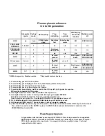
Pioneer plasma reference
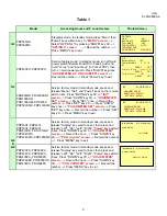
3rd to 5th generation
Integrator
mode
Factory
mode
Data backup
Trap
indication
Trap
override
PDP display
w/o media
receiver
Media receiver
kit
G3 PU
n/a
3 or 4
IC1204 Digital
video
Red blinks
fast
Enter factory
mode
E01
PDP-R03U-SK
PRO1000HD
PRO800HD
1, locked
3
6
n/a
n/a
n/a
n/a
PRO1000HDi
PRO800HDi
1
3
6
Red/green
flash, pause
9
n/a
n/a
G3 CMX
1
3
6
n/a
n/a
n/a
n/a
G4 PU
1*
5
7
Red and
green on
8
Red & green
boxes
PDP-R04U-SK
PRO-R04U-SK
G4 one piece
2 or n/a
5
7
Red and
green on
n/a or 8
n/a
n/a
G5 PU
1*
5
7
Red and
green on
8**
Red & green
boxes
PDP-R05U-SK
PRO-R05U-SK
PDP-AR05U-SK
G5 SX
10*
5
7
Red and
green on
8
n/a
n/a
*RS232 change only. Disables remote. **Only media receiver has trap.
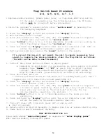
1) From standby, push menu, then power.
2) From standby, push display (shows call 1), hold display (shows call 2), menu.
3) From standby, push menu, then set, then power.
4) From standby, push set, then display, then power.
5) From standby, press display, wait 4 seconds; then left, up, left, right, power in sequence.
MR must be connected for PU models.
6) Use digital video for service. Data from RGB loads at power on.
7) Use digital video for service. In factory mode, info layer go to digital EEPROM.
Should be adjust N/G, backup OK. Push set, select data transfer-yes.
Goes to service part; select no. If replacing RGB or MR I/F data updates at power off.
8) Go to initialize layer of factory mode and hold display key until red led goes out.
9) Hold input until LEDs stay lit. Then push down, input, up, power in sequence.
10) Hold the VOLUME up or down key for 3-10 seconds. Then within 3 seconds hold the SPLIT key for 3-10 seconds.
Then within 3 seconds use the ENTER key to set to RS-232C (the baud rate last selected is chosen) or the
HOME MENU key to set to SR+.
3rd generation units that have power supply AXY1059-A to G are being covered for an upgrade to
AXX1064 (AXY1059-H). See bulletin for details. Serial # is on lower edge of front bezel, except for
PRO, which are adjacent to input jacks. An orange dot indicates upgrade is done. Customer
responsible for other repairs.
Power Supply Upgrade
18
Summary of Contents for Elite PRO-506PU
Page 2: ......
Page 8: ... 2 4 SI PG06003 A Warranty Claim Example 8 ...
Page 14: ...14 Quick Reference G 3 to G 8 Power Down Shut Down Trap Switch Reset Service Remotes ...
Page 23: ...23 Models PDP433PU PDP503PU Block Diagrams Shut Down Power Down Diagnosis ...
Page 30: ...30 Models PDP433CMX PDP503CMX PDP4300 PRO800HD HDI PRO1000HD HDI ...
Page 31: ...31 Block Diagrams Basic Service Factory Mode Shut Down Power Down Diagnosis ...
Page 48: ...48 Models PDP434CMX PDP504CMX PDP505CMX PDP4304 PDP4314 PDP5004 PDP5014 PRO810HD PRO1010HD ...
Page 49: ...49 Block Diagrams Operation LED Statuses Power Down Shut Down Diagnosis ...
Page 72: ...72 Models PDP436PU PDP506PU PRO436PU PRO506PU ...
Page 73: ...73 Block Diagrams Operation LED Statuses Shut Down Power Down Diagnosis System Reset ...
Page 82: ...82 Models PDP4270HD PDP4271HD PDP5070HD PDP5071HD PDP6070HD PDP6071HD PRO507PU PRO607PU ...
Page 87: ...87 Models PDP6070HD PDP6071HD PRO607PU Block Diagrams on the next two pages ...
Page 120: ...120 Scan IC Troubleshooting Blue Glue Removal IC Removal ...
Page 121: ......
Page 142: ...142 ...

